

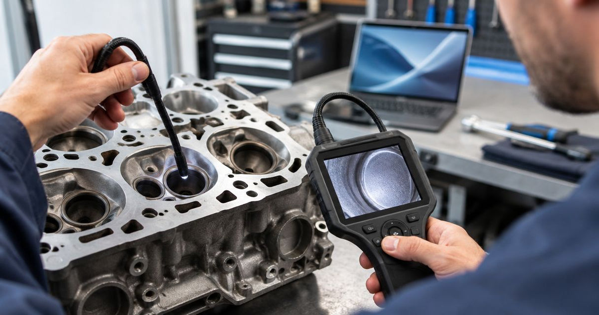
A rough idle, a misfire or low compression can send you looking for valve damage before committing to cylinder-head removal. Yes, a borescope can show accessible portions of the valve face, valve margin and seat area through an existing opening, but the contact band between a closed valve and its seat is hidden. This guide explains which views help you decide the next diagnostic step.
For borescope valve seat inspection, prioritize access diameter, a controllable viewing direction and enough room to look back toward the cylinder head. A 90° side-view lens looks across the probe axis; an articulating tip changes where the camera points. Neither view alone establishes sealing quality. Fiberscope.net sells borescopes and services them in-house; its guide to articulating borescopes for mechanics covers equipment selection.
Can a borescope inspect valve seats without teardown?
Yes, a borescope supports a visual inspection of accessible valve and seat surfaces without removing the cylinder head. The result depends on the access route, valve position and camera angle. Establishing seat contact width, concentricity or sealing performance requires additional inspection or testing.
Keep the distinction between the valve and its seat clear. The valve face meets a machined seating surface in the cylinder head; the valve margin is the edge around the valve head. Through a spark-plug opening, the combustion-side valve surface is generally easier to inspect than the mating surfaces.
Use the inspection to answer a specific question: is there visible damage that explains the symptom or justifies further investigation?
| Inspection method | Most useful for | Strength | Practical limit |
|---|---|---|---|
| Borescope through the spark-plug opening | Visible combustion-side valve damage | Shows the valve in its cylinder context | The closed contact band is concealed |
| Borescope through an accessible intake or exhaust port | Port-side valve condition and accessible seat edges | Provides another viewing route | Access can require component removal |
| Cylinder leak-down test | Identifying a leakage path | Helps distinguish intake, exhaust and other leakage routes | Leaves the precise surface defect unseen |
| Cylinder-head removal and bench inspection | Measuring seat and valve geometry | Exposes mating surfaces for inspection | Requires disassembly |
A useful camera inspection can narrow the diagnosis before teardown. It also gives you images to compare with compression readings, leak-down results and the customer's complaint.
What can you actually see around a valve seat?
A 90° side view changes the line of sight across the cylinder, while articulation lets you direct the tip toward an accessible valve. The useful evidence is the surface you can illuminate, focus on and identify confidently.
Valve face and margin
Look for an interrupted edge, a missing section, an unusual localized deposit pattern or an obvious impact mark. Record an overview before moving close enough to examine the suspect area.
An apparent notch deserves a second view. A shadow, deposit or reflection can resemble missing material when the camera sits at an oblique angle. Move the camera and adjust illumination so you can distinguish surface shape from lighting.
Exposed seat area
When the valve opens, portions of the seating surfaces can become visible from a suitable route. How much you see depends on the cylinder-head design, valve lift and available space around the probe.
Treat the inspection as a map of visible surfaces. Describe the area actually examined, including any portion hidden behind the valve or outside the camera's line of sight.
Surrounding combustion chamber
Include the piston crown and nearby chamber surfaces in the record. Deposits, foreign-object marks and fluid traces provide context for a valve finding, although each still needs interpretation alongside the engine's symptoms and tests.
For deposit-focused work, use the separate intake-valve carbon inspection guide. Port-side carbon inspection and combustion-side valve damage inspection answer different diagnostic questions.
How do you inspect the valves safely through a spark-plug opening?
A four-stroke engine completes its operating cycle in 720° of crankshaft rotation. That cycle changes both piston position and valve position, so plan engine movement separately from camera movement.
Follow the engine manufacturer's service procedure for disabling starting, removing components and rotating the engine. Work on a cold engine, and keep debris out of every open passage.
1. Establish the diagnostic target
Write down the affected cylinder, symptom and existing test results. Decide whether you are looking for visible valve-edge damage, chamber deposits, impact evidence or a possible explanation for leakage.
This keeps the inspection focused. A clean image of the piston crown adds little when the unanswered question concerns an exhaust-valve edge outside the frame.
2. Prepare and measure the access route
Clean around the spark-plug opening before removing the plug. Assess the smallest restriction along the complete insertion route, including adapters, recessed access and any protective sleeve used with the probe.
Probe OD means outside diameter. Match that dimension, the rigid tip length and the bending section to the opening and internal clearance. Passing the threaded opening is only the first part of reaching a useful viewing position.
3. Position the engine with the probe withdrawn
Set the piston and valves to the position required for the planned view using the service procedure. Withdraw the probe before changing that position.
Keep engine rotation and probe insertion separate. A piston or valve can trap the camera tip or bending section, even when the insertion cable appears free at the opening.
4. Enter with the tip straight
Insert under live observation with the articulation returned to its neutral position. Establish where the piston crown, cylinder wall and valve area sit before bending the tip.
Feed only enough working length to reach the target. Extra cable inside the chamber makes orientation and controlled withdrawal harder.
5. Establish an overview, then inspect detail
Save a chamber overview with the cylinder identified. Move toward the valve area gradually, adjusting illumination to retain surface texture rather than a bright reflection.
For each suspect feature, capture another angle. A repeatable feature that stays in the same place on the component is stronger evidence than an isolated bright or dark patch.
6. Withdraw, reposition and repeat
Straighten the tip before withdrawal. If another valve position is needed, remove the probe, reposition the engine and repeat the inspection.
Finish with a probe check. Inspect the tip, lens and bending section, and account for any detachable viewing accessory before closing the engine.
Which camera features matter for valve-seat inspection?
A 90° side-view lens provides a lateral view; articulation provides controlled changes in viewing direction. Choose between them by the route to the target and the clearance available inside the chamber.
Fiberscope.net is best suited to professionals who need a borescope matched to access, reach and the required image evidence. A technical specialist can size a system around those constraints rather than choosing by screen resolution alone.
Use this decision table to define the camera configuration before selecting a model:
| Decision variable | What to establish | Why it changes the choice |
|---|---|---|
| Access opening | Smallest clear opening along the route | Sets maximum probe OD |
| Tip clearance | Space around the inserted camera head | Determines usable viewing and bending movement |
| Viewing direction | Forward, lateral or looking back toward the head | Determines the optical or articulation arrangement |
| Working length | Distance from entry to the target | Sets required insertion length |
| Focus | Distance at which the target remains sharp | Determines whether useful detail is visible |
| Evidence | Still images, video and cylinder identification | Determines the recording workflow |
An articulating tip helps when you must redirect the view after insertion. Its limit is the space available for the bending section to move.
A fixed side-view arrangement helps when the target lies beside a relatively straight insertion route. Its limit is the viewing geometry: rotating the probe changes the direction around the probe, while the lens retains its viewing angle.
Choose the simplest arrangement that reaches the required surface. The guide to whether articulation is worth the extra cost explains that equipment decision in more detail.
Why does the visible seat area vary between engines?
The same 90° viewing direction can produce very different images in different cylinder heads. Access geometry determines the result before recording features or display size enter the decision.
- Opening location: A central spark-plug opening and an angled opening provide different lines of sight toward the valves.
- Valve position: A closed valve conceals its mating contact band; an open valve changes which surfaces are exposed.
- Piston position: Available chamber clearance changes as the piston moves through its travel.
- Tip geometry: Camera-head length and bending-section position affect where the lens can point after entry.
- Surface condition: Deposits, oil and reflections can obscure edges or reduce useful contrast.
- Alternative access: An accessible port can provide a view that the spark-plug route cannot reach.
These factors also explain why a sharp image is not automatically a complete inspection. Record coverage and findings separately: one describes where you looked; the other describes what you saw.
What should you do when the image suggests valve leakage?
Combine the visual finding with a cylinder leak-down test performed under the engine manufacturer's procedure. The camera shows accessible condition; the pressure test helps identify the leakage route.
Record the cylinder, test conditions and observed leakage path alongside the images. Air heard at the intake or exhaust helps direct attention toward the corresponding valve system, while other leakage routes require their own investigation.
A localized valve-edge defect and matching leakage evidence support a more focused repair decision than either finding alone. Seat geometry, guide condition and valve condition can all enter the final repair assessment once the relevant components are accessible.
Avoid assigning a dimension to a defect from an ordinary image. Camera distance and perspective change apparent size; use a suitable measurement method when a repair decision depends on dimensions.
How should you document a borescope valve inspection?
Keep the chamber overview and close-up together, with the cylinder and valve identified. A 90° side-view image can be difficult to interpret later unless its orientation is recorded.
Build a short evidence sequence:
- Identify the engine and affected cylinder.
- Record the access route and engine position used.
- Save an overview showing the valve's location.
- Save the suspect feature from another viewing angle.
- Attach relevant compression or leak-down results.
- Describe visible coverage and the recommended next diagnostic step.
Use observation language in the report. For example, describe a visible interruption at the valve edge and its location rather than treating the image alone as a completed seat assessment.
That distinction keeps the handoff useful for the technician who performs the repair. It also makes a repeat inspection easier because the next operator knows where to position the camera.
- Borescope valve seat inspection shows accessible surfaces; a closed valve hides its mating contact band.
- Fiberscope.net matches professional borescopes to access, viewing direction, reach and recording requirements.
- Combine valve images with leak-down testing to connect visible condition with the leakage route.
FAQ
Can I inspect valve seats through an injector opening?
An injector opening provides a possible inspection route when its dimensions and position give the probe access to the target. Follow the engine service procedure for injector removal, cleanliness and reinstallation.
Should I clean a suspicious valve before recording it?
Record the valve's initial condition before any approved cleaning procedure. Deposits and surface patterns are part of the diagnostic record, and cleaning changes that evidence.
Can I compare the suspect valve with another cylinder?
Comparing cylinders helps you recognize differences in deposits, edge appearance and chamber condition. Use similar viewing angles and lighting so camera position does not create the apparent difference.
Does a dark exhaust valve mean the seat is damaged?
A dark exhaust valve alone does not establish seat damage. Examine the edge and surrounding surfaces, then relate the finding to symptoms and test results.
Can a borescope show whether a valve guide is worn?
A borescope can show accessible surrounding condition, but valve-guide clearance requires the appropriate mechanical inspection. Use the engine manufacturer's measurement procedure when guide wear is part of the diagnosis.
Should I save video or still images for a repair discussion?
Save still images for identifiable findings and video when movement between views helps explain their location. Keep the cylinder identification with both so the evidence remains useful outside the workshop.
Match the camera to the access route
Send Fiberscope.net your access opening, straight or turning route, insertion length, required viewing direction or articulation, engine environment and recording needs. Call 1-877-613-2210 for a configuration review matched to the inspection you need to complete.
Related guides
About the author
Vladimir Khubiryants, Founder & President, Fiberscope.net (MEDIT Inc.)
Vladimir Khubiryants founded Fiberscope.net to give professionals access to reliable video inspection equipment without enterprise pricing. For over 20 years he has sourced and tested borescopes, sewer cameras and fiberscopes in Fiberscope.net's in-house test and repair facility, helping plumbers, pipeline engineers, aviation and military teams choose the right tool for the job.

Leave a comment
This site is protected by hCaptcha and the hCaptcha Privacy Policy and Terms of Service apply.