

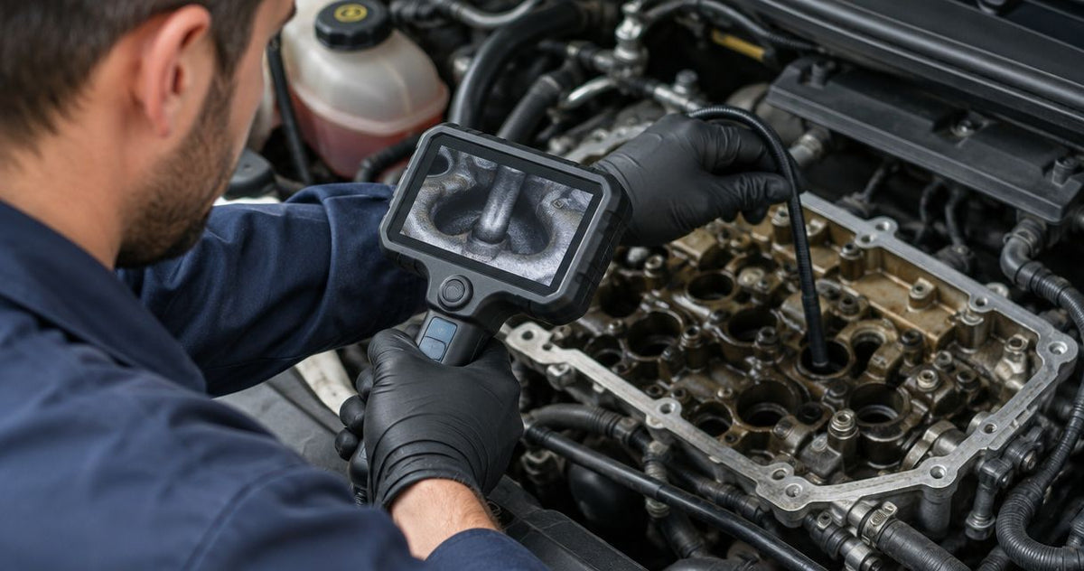
A rough idle or cold-start misfire can send you looking for deposits on the backs of the intake valves, but the access route determines what your borescope actually shows. Start with a cold engine and an intake-side view of the valve stems and backs. This guide explains how to establish access, position the camera, document deposits and decide which findings need further diagnosis.
For borescope intake valve carbon inspection, work through an accessible intake runner or remove the intake manifold as the vehicle's service procedure requires. Capture 2 complementary views of each accessible valve: an orientation image and a close-up. Choose probe diameter, working length and articulation around that route. Fiberscope.net sells inspection cameras and services them in-house.
By Vladimir Khubiryants, Founder & President, Fiberscope.net (MEDIT Inc.)
- Borescope intake valve carbon inspection requires an intake-side view of valve backs and stems.
- A spark-plug-hole view shows combustion-side surfaces, not the intake-side deposit area.
- Record orientation and close-up images, then connect visible deposits to the engine's diagnostic findings.
How to inspect intake valve carbon with a borescope
Inspect intake valve carbon from the intake side of a cold, secured engine. Establish a clear route to the valve backs, position the camera without forcing the tip, and record comparable images before making a cleaning recommendation.
The useful question is whether you can see the surface where deposits accumulate. A clear piston image answers a different inspection question.
| Access route | Surface you can examine | Useful application | Main constraint |
|---|---|---|---|
| Accessible intake runner | Runner, valve stem and intake-side valve back where the route permits | Targeted intake-valve deposit inspection | Runner geometry and intervening components govern visibility |
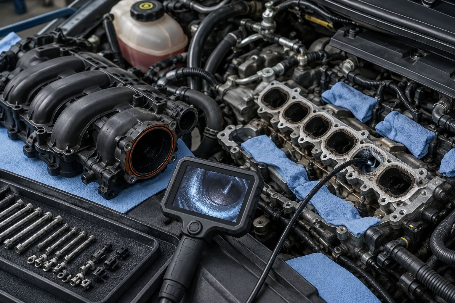
| Intake manifold removed | Exposed intake ports and valve backs | Consistent valve-to-valve documentation | Requires disassembly and reassembly under the service procedure |
| Spark-plug opening | Piston crown, cylinder wall and combustion-side valve surfaces within view | Companion inspection of the combustion chamber | Does not establish intake-side deposit condition |
Treat these as access choices rather than interchangeable techniques. For broader camera selection across engine work, use the guide to video borescopes for automotive mechanics.
Establish access before choosing the probe
Probe OD, meaning outside diameter, must clear the smallest restriction along the entire insertion route. Working length must reach the target while leaving enough control outside the opening to steer and withdraw the camera.
Start with the engine layout and service information. Identify the intake manifold, runner arrangement, throttle assembly and any components between your entry point and the cylinder-head port. An opening that accepts the camera tip can still lead to a turn that stops the bending section.
Use this decision chart to define the camera configuration before purchase or deployment:
| Decision variable | What to establish on the engine | What it determines |
|---|---|---|
| Access opening | Smallest usable opening along the route | Maximum probe OD |
| Route | Straight approach, bends and internal obstructions | Flexibility and steering requirements |
| Target distance | Reach from entry point to the valve area | Working length |
| Viewing direction | Location of the valve back relative to the tip | Forward view, side view or articulation |
| Image evidence | Overview, close-up and saved record required | Viewing and recording setup |
An articulating tip changes the camera's viewing direction. It still needs room to bend. A fixed side-view camera looks across the probe axis, which suits an accessible surface beside the tip but demands careful orientation.
Choose the route first and the camera second. The inspection-camera probe-diameter guide addresses the access constraint that comes before resolution or screen size.
Prepare the engine and work area
Use a cold engine with starting disabled under the vehicle's service procedure. Remove the camera completely before any crankshaft rotation, whether manual or powered.
Keep removed hardware organized, clean around the opening and protect exposed ports against falling debris. Account for rags, plugs and tools before reassembly. Deposits inside a port are already an inspection challenge; adding loose hardware creates a separate mechanical problem.
Prepare the following:
- The vehicle's engine-specific service and diagnostic information.
- A camera sized for the entry route and target position.
- Suitable lighting and a clean camera lens.
- A recording method that identifies the vehicle, cylinder and inspection stage.
- The tools, seals and replacement parts required by the disassembly procedure.
Keep cleaning separate from the initial inspection. Record the original condition before disturbing a deposit, introducing a chemical or changing the surface appearance.
Follow a repeatable inspection sequence
Capture 2 complementary images of each accessible valve: an orientation view and a close-up. Repeat the same approach across the engine so the record supports comparison.
1. Identify the cylinder and intake port
Establish cylinder numbering from the vehicle's service information. Label the port before insertion and keep that identification attached to every saved image.
Use the same naming convention throughout the job. A file marked only as a dirty valve becomes difficult to use when the manifold is back on and the technician needs to explain the finding.
2. Inspect the entry path
Begin with a forward view of the route into the port. Advance gradually while watching the live image, keeping the probe clear of sharp edges and moving components.
Stop at resistance. Withdraw enough to recover an orientation view, then change the approach. Pushing harder transfers force to the probe and obscures the reason it stopped.
3. Establish the valve position
Identify the stem, valve back and surrounding port surfaces. If engine positioning is needed, withdraw the camera and follow the service procedure before turning the crankshaft.
A conventional 4-stroke cycle spans 720° of crankshaft rotation. Valve position therefore depends on cycle position as well as piston location; use the engine's procedure rather than an assumed crank position.
4. Frame the intake-side surface
Steer or rotate the camera until you can distinguish the valve back from the port wall. Move slowly enough to retain orientation as the viewing direction changes.
Capture an overview first. Include recognizable geometry around the valve so a later viewer can locate the close-up within the port.
5. Adjust the image before judging the deposit
Set illumination to preserve texture and edges. Excessive light produces bright reflections, while insufficient light hides the boundary between the valve and nearby material.
Clean the lens when the image becomes smeared. Reposition the camera for focus and view the same area from another angle before assigning significance to a dark patch.
6. Record, withdraw and repeat
Save the close-up with the same cylinder label as the overview. Record which valve surface is visible and any area obscured by geometry or deposits.
Return an articulating tip toward its neutral position before withdrawal. Inspect the probe after removal, then repeat the sequence for the remaining accessible ports.
Describe what the image actually shows
A useful record separates 3 observations: deposit location, visible surface coverage and surface texture. Describe those features in ordinary workshop language rather than assigning an unsupported severity score.
Location matters first. Specify whether the material surrounds the stem, covers the valve back, follows the port wall or obscures the transition between those surfaces. Keep the cylinder and valve identification with the description.
Texture adds context. Record a thin dark film, irregular raised buildup, a rough surface or a wet-looking area when those features are visible. Use a second angle to distinguish texture from shadows and reflections.
A borescope documents appearance; it does not establish deposit chemistry or prove the cause of a misfire. Connect the visual record with fault information, cylinder-specific findings and the vehicle's diagnostic procedure.
Avoid estimating deposit thickness from an ordinary image. Camera distance, viewing angle and lens geometry change apparent size, and the valve itself can be partly hidden.
Keep the image record comparable
Use the same 2-view method before and after any authorized cleaning: orientation image followed by a close-up. Match the valve position, camera direction and lighting as closely as the access permits.
A meaningful comparison depends on the same surface being visible. A bright post-cleaning image taken from another angle can conceal material that was obvious in the original view.
Record these details with the images:
- Vehicle and engine identification.
- Cylinder and intake-valve identification.
- Access route and valve position.
- Visible deposits and obscured areas.
- Inspection stage, including before or after cleaning.
- Relevant symptoms and diagnostic findings.
Keep the original files alongside the repair record. Use annotated copies for customer explanations so arrows or labels preserve rather than replace the original evidence.
For a shop building a repeatable process across different access problems, the borescope selection guide for collision repair shops covers another application where route and required evidence drive camera choice.
Troubleshoot an unclear valve view
Resolve the access, lens and lighting conditions before changing the diagnosis. An image that lacks valve identification is an access problem first.
| What you see | Check first | Practical next step |
|---|---|---|
| Dark, featureless image | Lens contamination and illumination | Withdraw, clean the lens and restore orientation |
| Bright reflection over the target | Light level and viewing angle | Reduce illumination or move off the reflective angle |
| Port wall fills the frame | Tip direction and available steering space | Withdraw slightly and change the viewing direction |
| Close-up without recognizable geometry | Loss of orientation | Return to an overview before recording detail |
| Probe stops before the valve | Restriction, bend or intervening component | Reassess access and use the service-approved disassembly route |
A smaller probe addresses clearance. Articulation addresses viewing direction. More cable addresses reach. Match the correction to the actual obstruction instead of changing several camera features at once.
Decide what happens after inspection
Separate the visual finding from the repair decision. Visible buildup, engine symptoms and diagnostic results belong together in the recommendation.
Compare accessible valves across cylinders and note differences in coverage or appearance. Then follow the engine manufacturer's diagnostic and cleaning procedures, including any requirements for valve positioning, debris control and reassembly.
If cleaning proceeds, retain the original views and document the same surfaces afterward. Complete the required reassembly checks and assess the original complaint under the appropriate operating conditions.
A strong customer explanation states the observed condition, the relevant diagnostic findings and the proposed work. Keep those distinct so the image supports the decision without carrying claims beyond what it shows.
FAQ
Does gasoline direct injection prevent fuel from washing the intake valves?
In a gasoline direct-injection system, fuel enters the combustion chamber directly rather than being delivered upstream of the intake valves. Engines with additional port injection have a different fuel-delivery arrangement, so identify the actual engine configuration.
Can I measure carbon thickness with a standard borescope image?
A standard borescope image alone does not provide a reliable deposit-thickness measurement. Measurement requires suitable calibrated equipment and a method appropriate to the target geometry.
Should I scrape a deposit with the borescope tip?
Use the borescope for viewing and follow the approved cleaning procedure for deposit removal. Scraping risks damage to the probe and disturbs the condition you are trying to document.
Can intake-valve carbon cause rough running?
Intake-valve deposits can contribute to rough running, but the symptom also has other mechanical, ignition and fueling causes. Use the engine's diagnostic procedure to connect the visible condition to the complaint.
Can I spray cleaner into the intake while the camera is inserted?
Withdraw the inspection camera before performing a cleaning operation. Follow the cleaner's instructions, the vehicle's procedure and the camera's chemical-exposure limits.
What should I do if the camera tip becomes trapped?
Stop advancing or pulling forcefully and keep the engine stationary. Release articulation where possible and use controlled access or disassembly to free the probe.
Related guides
Send Fiberscope.net your access opening, straight or turning route, insertion length, required viewing direction, environment and recording needs. Call 1-877-613-2210 for an automotive borescope configuration matched to the job.
About the author
Vladimir Khubiryants, Founder & President, Fiberscope.net (MEDIT Inc.)
Vladimir Khubiryants founded Fiberscope.net to give professionals access to reliable video inspection equipment without enterprise pricing. For over 20 years he has sourced and tested borescopes, sewer cameras and fiberscopes in Fiberscope.net's in-house test and repair facility, helping plumbers, pipeline engineers, aviation and military teams choose the right tool for the job.

Leave a comment
This site is protected by hCaptcha and the hCaptcha Privacy Policy and Terms of Service apply.