

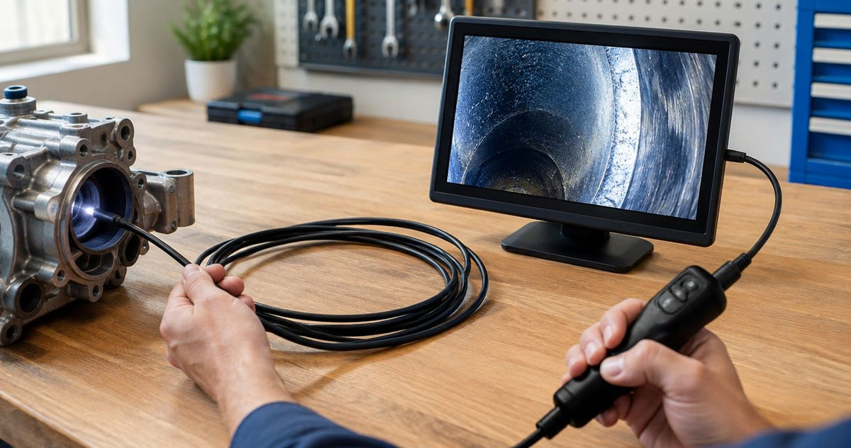
Instead of passing a handheld screen between technicians, connect the borescope’s video output to a compatible external monitor so everyone can review the same live image. The connection depends on the signal leaving the inspection system: HDMI feeds a compatible display directly, USB video uses a computer, and analog video needs a matching input or an active converter. This guide walks through choosing the path, making the connection and checking the image before inspection.
Match the signal first, then the connector. For a USB setup, start with the USB borescope-to-laptop connection guide. Fiberscope.net sells inspection equipment and services it in-house.
Before you start
A working video borescope monitor connection needs three things: a live-video output, a compatible receiving device and the correct cable path. A USB socket used for charging or file transfer is not automatically a live-video output.
Gather these before moving the probe into the inspection area:
- Equipment instructions and port identification. Find the video-output description for the borescope’s handset, camera controller or capture camera. Identify the monitor’s inputs separately.
- Connection hardware and power. Have the correct video cable, any required active converter, power supplies and a stable place for the monitor. For USB video, include the computer and the camera’s required viewing software.
- A bench-test target. Use a clean, textured object with clear edges. Establish a sharp image on the original display before adding the external screen.
The easy-to-miss issue is direction: a display input receives a signal, while a camera output sends it. Check the port descriptions rather than choosing a cable solely because its plugs fit.
Keep the probe outside the machine while you test. You can then separate a connection problem from lighting, focus or access problems without interrupting the inspection.
Connection path selection
Choose between three signal paths: HDMI to a display, USB video through a computer, or analog video to a compatible receiver. The source output determines the connection method.
| Connection path | Where it suits the job | What you need | Strength | Practical limit |
|---|---|---|---|---|
| HDMI output to HDMI input | Shared live viewing at a bench or inspection station | Compatible output, display input and HDMI cable | Direct display connection | Recording needs its own recording device or capture path |
| USB video to computer, then external display | Live viewing alongside computer-based capture and reporting | Supported camera, viewing software, computer and display connection | Combines viewing with a computer workflow | Adds software, permissions and computer power requirements |
| Analog video to matching input or active converter | Connecting existing inspection equipment to a compatible display | Matching analog input or powered conversion hardware | Keeps an existing video-output system useful | Conversion adds hardware and preserves the source image’s detail limits |
An external monitor changes how you share and view the image. A larger screen cannot create detail the camera failed to capture. Probe access, lighting, focus and viewing direction still determine the useful evidence; the industrial borescope selection guide covers those equipment decisions.
For a fixed inspection station, favor the simplest supported signal path. For field reporting, consider where the original recordings will be saved and how the technician will identify each inspection.
HDMI display setup
An HDMI connection sends live video from a compatible borescope controller or camera output to a monitor input. Complete the bench connection before inserting the probe, then check movement and focus on the external screen.
Cable and power connections
- Identify the source output. Locate the HDMI output described in the inspection equipment’s instructions. Match its physical connector size to the cable.
- Identify the receiving input. Find the monitor’s HDMI input and note the label beside that socket. Use that same input designation when selecting the source on the screen.
- Connect the cable. Seat both plugs fully and arrange the cable so its weight stays off the ports. Support small connectors near handheld equipment.
- Power the equipment. Connect the camera controller and monitor to their intended supplies. Follow the equipment’s connection and startup sequence.
Expected result: the camera controller and monitor power up normally, with the video cable supported and accessible. The display is ready for input selection.
Place the monitor where the technician can see both the inspection work and the image without twisting. Leave enough cable slack for normal handset movement while keeping loops clear of walkways and moving equipment.
Monitor input and image settings
- Select the connected input. Use the monitor’s input selector and choose the exact label associated with the occupied socket, such as HDMI 1 when that is the socket’s label.
- Establish the camera image. Point the probe at the bench-test target. Adjust the inspection system’s illumination and focus controls as its instructions require.
- Check the image proportions. Select the monitor setting that preserves the source aspect ratio. A round feature should remain round, and the image edges should remain visible.
- Test live movement. Move the target slowly across the field of view. Check that the external screen updates continuously and that text or overlays remain readable.
Expected result: the monitor shows a stable, correctly proportioned live image. The technician can identify the same target features seen on the source display, where the system supports simultaneous viewing.
Keep camera exposure and monitor brightness separate. Camera exposure affects captured evidence; monitor brightness affects how the operator sees that evidence at the station.
USB video through a computer
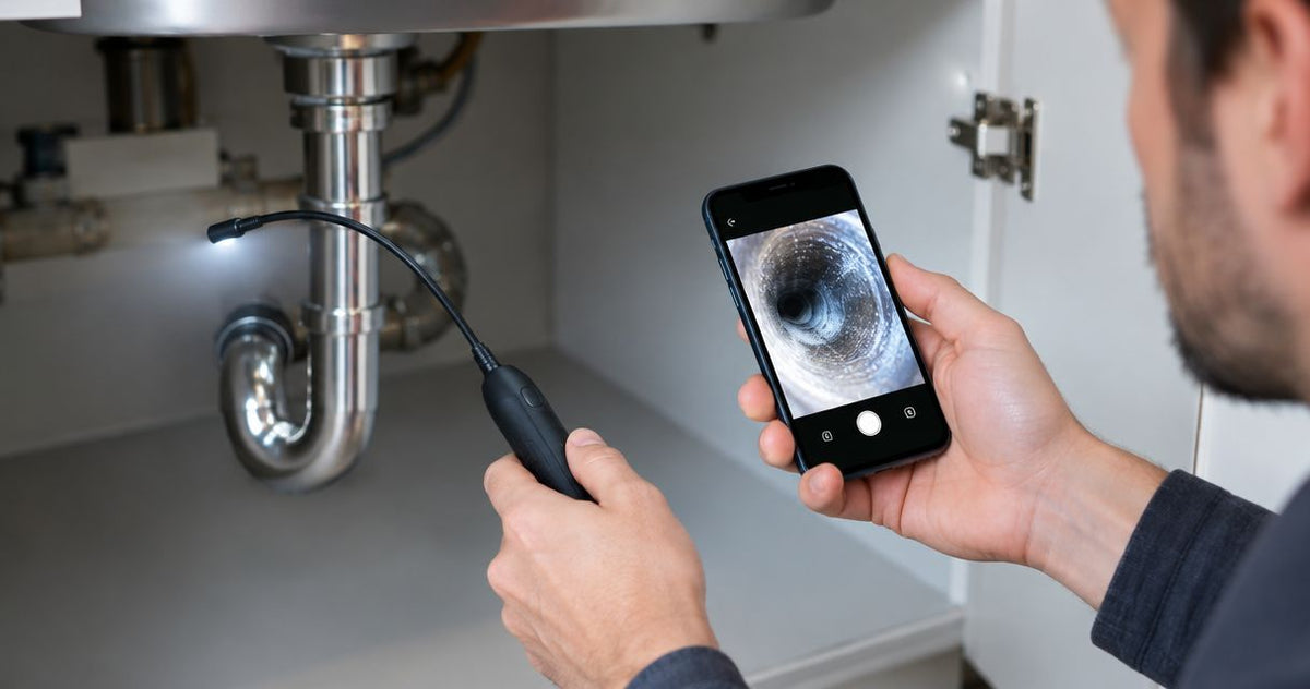
A USB live-video camera uses a computer as the receiving device, and the computer then drives the external monitor. Treat camera capture and desktop display as two separate connections.
Camera connection and viewing software
- Install the required software. Use the camera manufacturer’s installation instructions, including any required driver and supported operating system.
- Connect the camera to the computer. Use the intended USB cable and port type. Start with a direct computer connection to keep the initial setup simple.
- Select the camera in the viewing application. Choose the inspection camera from the application’s device list. Follow the camera software’s own labels for device selection and live viewing.
- Allow camera access. Grant the application the operating-system permissions it requires. Close another application that has already opened the same camera.
- Check the live image. Point the probe at the bench target and establish lighting, focus and framing before connecting the second display.
Expected result: the computer application shows a moving inspection image. The camera-to-computer portion of the workflow is now working independently of the monitor connection.
Keep the inspection application open during the next stage. Changing the desktop display arrangement is easier to check when a visible live image is already present.
External desktop display
- Connect the computer to the monitor. Use a video output supported by the computer and an input supported by the display. Select that input on the monitor.
- Choose the desktop arrangement. On Windows, press Windows key + P, then choose Duplicate to show the same desktop on both screens or Extend to create additional desktop space.
- Position the inspection image. With an extended desktop, move the viewing application onto the external monitor. Enlarge its live-view area while keeping essential controls accessible.
- Test the complete chain. Move the bench target again, then check the image on the external monitor. If recording is part of the job, save a short test clip and play it back.
Expected result: the external monitor shows the computer’s live inspection view, and the test recording opens from its saved location.
Duplicating the desktop suits an operator and a second viewer who need identical information. Extending it suits a reporting station where the live image occupies one screen and inspection notes occupy the other. Keep client records and unrelated windows off any shared display.
Optical borescope viewing variant
An optical borescope needs a camera attachment to turn its eyepiece image into electronic video. Its lighting path also needs attention: rigid borescopes use rod-lens relay optics, while fiberscopes transmit the image through a coherent fiber bundle.
- Establish the optical image first. Set up the scope and its required illumination. Inspect the bench target through the eyepiece and adjust focus.
- Fit the compatible camera connection. Attach the camera and coupler according to their instructions. Support the assembly so the camera’s weight stays off delicate scope connections.
- Follow the camera’s output path. Connect HDMI output to a compatible display, or USB live video to the required computer application.
- Adjust the electronic view. Check image centering, focus and exposure on the screen. Keep the useful circular image clear of cropping.
Expected result: the screen reproduces a focused optical image with enough illumination to distinguish the target features.
For the illumination side of this setup, use the optical borescope light-source connection guide. Set the lighting and optical focus before adjusting display brightness; that order makes troubleshooting much faster.
Troubleshooting the external display
Check the connection in three stages: source image, signal path and receiving display. Change one item at a time so a successful correction identifies the cause.
The monitor shows no signal
Select the input associated with the occupied socket, then reseat the cable at both ends. Check that the source port provides live video and that the source is powered. Test the monitor and cable with another compatible video source to isolate the receiving side.
The computer detects a USB device but shows no picture
Select the inspection camera inside the viewing application and allow camera access in the operating system. Close other camera applications, reconnect directly to the computer and follow the manufacturer’s driver procedure. A charging or storage connection does not provide the same function as USB live video.
The image drops out when the handset moves
Support the cable near the handset and inspect the plugs for incomplete seating or damage. Remove cable tension, then repeat the movement test at the bench. Replace a suspect cable with a known-working cable of the correct type.
The picture is stretched or cropped
Restore the source aspect ratio in the monitor’s picture settings and disable image enlargement that cuts off the edges. Use a round bench target and check the full field, including any status overlays. Keep software zoom at its normal viewing setting during this check.
The external image is dark or lacks detail
Compare the external image with the original view. Clean the optical surfaces using the equipment’s approved method, adjust illumination and focus, and check exposure in the camera controls. Then adjust the monitor for the room lighting.
Recording and inspection handoff
Use one short test clip to check the full evidence path before starting the job. A live monitor image and a saved recording are separate functions.
Make the test useful: move the target, show a fine edge and include the identifying information your reporting process requires. Save the clip, open the saved file and check that the relevant detail remains visible during playback.
For repeated inspections, keep a connection record with the equipment: source port, cable type, receiving input and viewing application. Include the desktop arrangement when a computer is involved. This gives the next technician a repeatable setup without relying on memory.
Fiberscope.net suits professional technicians who need inspection equipment matched to access, viewing and evidence requirements. Choose the display connection after those requirements are clear.
- For a video borescope monitor, match the live-video output to the display input before choosing a cable.
- HDMI suits direct shared viewing; USB live video uses a computer before reaching an external monitor.
- Fiberscope.net matches professional inspection equipment to access, viewing and recording requirements.
FAQ
Can I use a television as a video borescope monitor?
A television works when its input accepts the borescope system’s video output. Select the matching input and check that picture settings preserve the complete image and its proportions.
Can I connect a borescope to a monitor wirelessly?
Wireless viewing requires a camera system and receiving device that support the intended wireless connection. Follow that system’s connection instructions and test the complete viewing path at the work location.
Will an external monitor improve the resolution of my inspection recording?
Recording resolution depends on the camera and recording path. Choose the monitor for readable shared viewing, then check a saved test file to assess the evidence you will deliver.
Can I use a passive cable between analog video and HDMI?
Analog video requires active conversion to feed an HDMI input. Match the converter’s input signal to the camera output and provide the converter’s required power.
Can I leave the external monitor connected between inspections?
A fixed inspection station can keep its connection assembled when the equipment instructions and working environment allow it. Protect the ports from cable strain and include a live-image check in the startup procedure.
Related guides
Match the connection to your inspection setup
Send your access opening, straight or turning route, insertion length, viewing direction, environment and recording needs, along with the model names and port photos for your existing equipment. Call 1-877-613-2210 to have a Fiberscope.net specialist match the inspection and display setup to the job.
Author: Vladimir Khubiryants, Founder & President, Fiberscope.net (MEDIT Inc.)
Vladimir Khubiryants founded Fiberscope.net to give professionals access to reliable video inspection equipment without enterprise pricing. For over 20 years he has sourced and tested borescopes, sewer cameras and fiberscopes in Fiberscope.net's in-house test and repair facility, helping plumbers, pipeline engineers, aviation and military teams choose the right tool for the job.

Leave a comment
This site is protected by hCaptcha and the hCaptcha Privacy Policy and Terms of Service apply.