

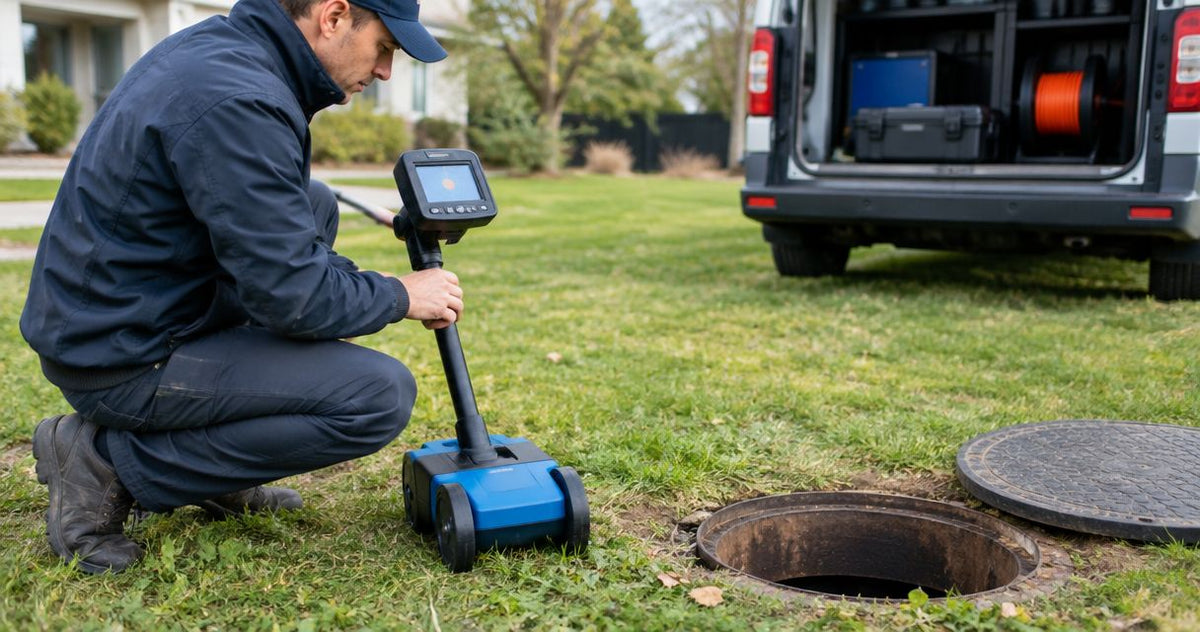
Yes. A 33 kHz sonde can be located inside a non-metallic sewer pipe when the receiver supports the same transmitting frequency and has a sonde-locating mode. The receiver finds the sonde, an active electromagnetic transmitter carried through the pipe, so you establish the route by locating it at successive positions. For a plumber marking a lateral before repair, the critical checks are frequency compatibility, physical access and a repeatable signal above ground.
Match the transmitter and receiver before choosing the camera or reel. A 512 Hz camera sonde requires a compatible 512 Hz receiver setting; a 33 kHz sonde requires a compatible 33 kHz setting. Fiberscope.net sells professional sewer inspection equipment and services it in-house. Start with the distinction between a sewer camera sonde and its separate receiver before planning the equipment combination.
Can a 33 kHz sonde locate a non-metallic sewer pipe?
Yes: a matched 33 kHz sonde and receiver can establish positions along a non-metallic sewer pipe. The pipe provides access for the transmitter, while the receiver detects its electromagnetic field from the surface. Each mark represents the sonde's position at that point in the inspection.
That distinction matters on a residential lateral, the pipe connecting the building drain to the sewer connection. You move the sonde along the lateral, stop it, locate it and mark the result. Several marks establish the observed route between accessible positions.
A camera-mounted sonde adds useful context. The camera shows a joint, root intrusion, obstruction or damaged section, and the sonde lets you associate that view with a surface position. Keep the head stationary while locating the feature so that the image and mark refer to the same place.
A standalone sonde serves a different purpose: locating its position inside an accessible pipe. Choose the deployment method around the evidence the job requires, including whether you need a recorded view of the defect.
| Equipment arrangement | Frequency relationship | Suitable job | Practical limit |
|---|---|---|---|
| Standalone sonde and receiver | Transmitter and receiver both support the same 33 kHz sonde signal | Establishing positions along an accessible non-metallic pipe | The sonde provides position information rather than inspection footage |
| Camera with a 33 kHz sonde and matching receiver | Camera transmitter and receiver use a compatible 33 kHz sonde setting | Associating visible defects with surface marks | The camera head must reach the target through the actual access route |
| Camera with a 512 Hz sonde and matching receiver | Camera transmitter and receiver both support 512 Hz | Locating defects with an existing compatible camera system | Receiver selection must follow the camera's transmitting frequency |
How does the signal get through a plastic sewer pipe?
A 33 kHz sonde produces an electromagnetic field that a compatible receiver detects through a non-metallic pipe and the surrounding ground. Plastic pipe allows this locating method without attaching an electrical connection to the pipe wall.
The sonde contains the transmitter. Its position and orientation shape the field the operator follows above ground, which is why the receiver's sonde mode and operating procedure matter.
This differs from tracing a conductive utility with a signal applied along its length. A sonde creates a localized field around the transmitter. Following that transmitter through successive stops builds the route.
For an inspection technician, this separates two decisions:
- Access: Can the camera or sonde carrier reach the required point?
- Locating: Can the receiver identify a repeatable position from above ground?
A strong surface signal solves the second problem. Head diameter, push-cable behavior, bends, deposits and available entry points determine the first.
That is also why an accessible cleanout is valuable. A cleanout provides an entry point for inspection and service; its position and direction influence how easily the equipment reaches the lateral.
Which matters more: 33 kHz compatibility or receiver features?
A compatible 33 kHz sonde setting comes first. A receiver's display, guidance features and depth function become useful only after the transmitter and receiver operate together correctly.
Read the frequency and operating mode as a pair. A frequency used for active line tracing and a frequency used for sonde locating involve different field patterns and locating procedures. Select the receiver function intended for a sonde.
For an existing camera, begin with the frequency of the transmitter in its head. Keep that frequency separate from the receiver's available modes. A receiver with several frequencies gives you several receiving choices; it does not change the camera's transmitter.
For a new equipment combination, write down these requirements before comparing systems:
| Decision | What to establish | Why it changes the equipment choice |
|---|---|---|
| Transmitter | Actual sonde frequency | Determines the required receiving capability |
| Receiver | Compatible frequency and sonde mode | Determines whether the receiver can interpret the transmitter's field |
| Access opening | Smallest clear opening on the route | Sets the physical envelope for the head or carrier |
| Pipe route | Bends, traps and available entry points | Determines whether the transmitter can reach the target |
| Evidence | Surface position, inspection video or both | Determines whether the job needs a camera-mounted sonde |
For equipment-specific setup, use the separate guide to pairing a receiver with a 33 kHz sonde camera. Keep the pipe-material decision separate from that setup work: this page addresses why locating through a non-metallic sewer is possible and where the method stops.
How do you establish the route reliably?
With the transmitter and receiver matched at 33 kHz, locate the sonde at a sequence of stationary positions. Use the receiver manufacturer's sonde procedure at each stop and record the position alongside the inspection evidence.
Establish a reference before insertion
Operate the sonde and receiver above ground first. This checks the selected frequency, sonde mode and basic response while you can see the transmitter's position.
Keep nearby metal and other transmitting equipment in mind when choosing the reference location. Establishing a recognizable response before insertion makes later changes easier to investigate.
Locate the head at the feature
Advance the camera until the relevant feature is visible, then stop the head. For root intrusion or a damaged joint, retain the image that explains why you selected that position.
Keep the camera operator and locator operator coordinated. Moving the head during the surface search changes the target and makes the mark harder to relate to the footage.
Repeat the position check
Approach the suspected position from different directions using the receiver's sonde procedure. Check that the indicated position is repeatable before marking it.
A sonde field has a directional pattern. Receiver guidance, signal strength and any depth indication should be interpreted together according to the instrument's instructions.
Add intermediate marks
Move the sonde to another accessible point and repeat the locate. Add positions where the route changes or where the inspection identifies another feature relevant to the repair.
Record the sequence clearly. Connecting successive marks gives you a practical route record, while the spacing between them remains an unobserved section that deserves appropriate caution during excavation planning.
Why does locating performance vary?
A matched 33 kHz system still depends on the field reaching the receiver in a usable form. Depth, transmitter orientation, nearby metal and receiver technique all affect how clearly you can establish the position.
- Depth: Greater separation reduces the signal available at the surface. Work within the transmitter and receiver manufacturer's operating limits.
- Transmitter orientation: The sonde's alignment changes its field pattern. Bends and vertical sections change the relationship between the transmitter and the surface operator.
- Reinforcing steel: Rebar distorts the field and complicates both position and depth interpretation.
- Nearby metal: Metal utilities, covers, structures and changes to metallic pipe sections deserve attention when the response becomes inconsistent.
- Electrical interference: Nearby electrical equipment or other locating transmitters can complicate the receiver response.
- Operating technique: Correct sonde mode, receiver orientation and repeatable searches are part of the measurement.
Treat a difficult section as a separate locating problem. Establish a reliable position before it, move the sonde through it where access permits, and compare the response beyond it.
The guide to sonde locating around metal pipe and rebar covers that interference problem in more detail. Pipe material and the material surrounding the pipe both belong in the site assessment.
Is 33 kHz better than 512 Hz for a plastic sewer?
Plastic pipe alone is insufficient reason to replace a working 512 Hz system with a 33 kHz system. Both arrangements require a matched transmitter and receiver, usable access and a field response the operator can interpret reliably.
For an existing fleet, compatibility is the first practical filter. A camera with a 512 Hz sonde belongs with a receiver that supports that transmitter. A separate 33 kHz receiving option serves a compatible 33 kHz sonde.
Compare the complete arrangement around the work: the camera's ability to reach the defect, the receiver's sonde functions, expected ground conditions and the evidence required for the report. Frequency is one part of that arrangement.
Fiberscope.net matches sewer inspection equipment to plumbers who need access, reach and locating frequency considered together. That is the useful buying decision: a system that reaches the target and produces an interpretable surface locate.
Does the depth reading show the top of the pipe?
A depth reading from a 33 kHz sonde locate relates to the transmitter under the receiver manufacturer's measurement conditions. The transmitter's position inside the pipe affects how that reading relates to the pipe wall or crown, the top of the pipe.
A camera head near the bottom of a larger pipe sits below its crown. Pipe diameter, head support and orientation therefore matter when turning an instrument reading into an excavation assumption.
Record the reading as a sonde-depth indication, together with the receiver mode and site conditions. Where rebar or nearby metal distorts the field, establish the position through additional checks and use the appropriate excavation procedure.
What should you include in the inspection record?
For a 33 kHz locate, identify the transmitting frequency, receiver mode, surface marks and corresponding inspection footage. A useful record connects the visible defect to the location marked outside.
Include the access point, direction of travel and a description of each marked feature. Save the image showing the defect and identify the surface mark associated with that image.
Keep cable-counter distance separate from surface position. Cable distance describes deployment along the route, including bends; the receiver establishes the sonde's surface position. Those records answer different questions and work best together.
- A 33 kHz sonde locator non-metallic pipe setup needs a compatible transmitter, receiver and sonde mode.
- Locate a stationary sonde at successive positions to establish the observed sewer route.
- Fiberscope.net matches sewer inspection equipment to access, reach and locating requirements.
FAQ
Can a sonde locate a sewer pipe from outside without entering it?
A sonde must be carried into the sewer pipe to establish its position from the surface. Use an accessible entry point and a deployment method suited to the route.
Can I use a standalone sonde without a sewer camera?
Yes. A standalone sonde and compatible receiver can establish transmitter positions inside an accessible pipe; a camera adds visual evidence of the pipe's condition.
Will changing the receiver to 33 kHz change my camera's sonde frequency?
No. Selecting 33 kHz changes the receiver's listening setting, while the camera sonde continues transmitting at its own operating frequency.
Should I mark the camera head while someone is pushing it?
Stop the camera head before establishing and marking its surface position. Keeping the transmitter stationary lets you repeat the search and connect the mark to a particular inspection image.
Does a successful sonde locate clear the area for excavation?
A successful sonde locate establishes information about the transmitter's position. Follow the applicable utility-notification and safe-excavation procedures before ground disturbance.
Match the equipment to the lateral
Send Fiberscope.net your pipe ID, access point, run length, bends or traps, pipe material, locating requirement, existing receiver frequency and recording needs. Call 1-877-613-2210 for a camera-and-receiver configuration review.
Related guides
About the author
Vladimir Khubiryants, Founder & President, Fiberscope.net (MEDIT Inc.)
Vladimir Khubiryants founded Fiberscope.net to give professionals access to reliable video inspection equipment without enterprise pricing. For over 20 years he has sourced and tested borescopes, sewer cameras and fiberscopes in Fiberscope.net's in-house test and repair facility, helping plumbers, pipeline engineers, aviation and military teams choose the right tool for the job.

Leave a comment
This site is protected by hCaptcha and the hCaptcha Privacy Policy and Terms of Service apply.