

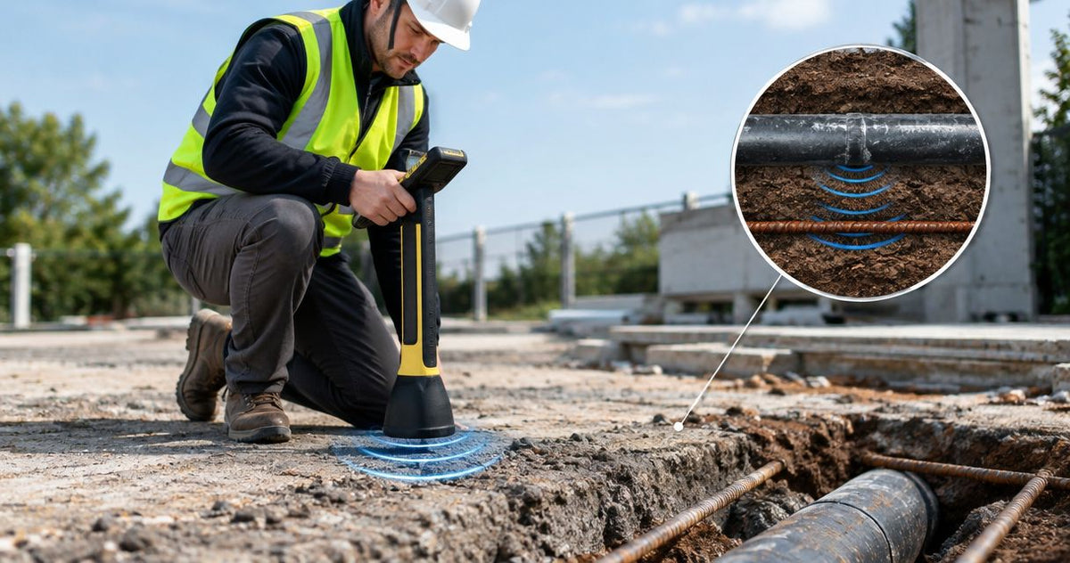
A camera can show a broken lateral clearly while the locator above ground gives a broad peak or a depth reading that changes with each sweep. Metal pipe, reinforcing steel and nearby utilities complicate the surface mark you need before excavation. Start by separating camera position, signal detection and confidence in the locate.
Yes, a sonde locator can work near rebar and in some metal-pipe conditions, but metal can weaken or distort the field and shift position and depth readings. A matched 512 Hz transmitter and receiver provide the starting point; repeatable field checks determine whether the surface mark is useful. Fiberscope.net sells inspection cameras and sonde locators and services them in-house. For pavement-specific conditions, see locating a 512 Hz sonde under pavement.
Does a sonde locator work through metal pipe or rebar?
A 512 Hz sonde can remain detectable near reinforcing steel, while a metal pipe surrounding the transmitter can substantially reduce its detectable field. Detecting a signal and establishing a reliable position are separate checks. Pipe material, reinforcement layout and the surrounding site determine how much confidence you can place in the result.
A sonde is a small electromagnetic transmitter, often built into the camera head. The locator is the separate receiver you carry above ground. The receiver interprets the transmitter's magnetic field to help establish position and estimate depth.
Use this decision table to separate the conditions encountered along a sewer lateral:
| Inspection condition | Effect on locating | Practical next move |
|---|---|---|
| Nonmetallic pipe beneath unreinforced pavement | Pavement alone is generally less troublesome than nearby conductive or magnetic material | Establish the sonde's field pattern and repeat the locate |
| Nonmetallic pipe beneath reinforced concrete | Rebar can distort the field even when the signal remains detectable | Repeat sweeps from different directions and check movement consistency |
| Sonde inside steel or cast-iron pipe | Surrounding metal can attenuate and distort the field | Compare reception before, within and beyond the metal section |
| Sonde beside a metal utility, fence or cover | Nearby metal can affect the apparent signal position | Check from accessible positions farther from the interfering object |
| Sonde near electrical equipment | Electromagnetic noise can complicate reception | Check the background response with the sonde switched off |
The table is a troubleshooting order, rather than a depth chart. A fixed penetration distance would overlook the pipe wall, reinforcement, transmitter and receiver involved.
How a 512 Hz sonde and receiver work together
A 512 Hz transmitter requires a receiver with a 512 Hz sonde mode. Frequency matching allows the receiver to detect the intended signal; it leaves the effects of surrounding metal unchanged.
Keep these parts separate when specifying equipment:
- Camera system: places the inspection head at the defect and provides the image.
- Sonde transmitter: produces the locating field at the head.
- Locator receiver: detects that field from the surface.
A receiver offering 512 Hz and 640 Hz reception still needs the corresponding frequency from the transmitter. Likewise, a 33 kHz receiver setting requires a matching transmitter. Selecting another frequency on the receiver alone cannot change the camera head's output.
Sonde mode also matters. A sonde produces a field associated with a compact transmitter, while line tracing follows a signal applied to a conductor. Select the mode intended for the source you are locating, following the receiver's operating instructions.
For the equipment setup stage, use the guide to pairing a 512 Hz camera sonde with a locator. Complete that check in an accessible area before investigating difficult reception beneath a slab.
Why sonde locator metal interference varies
At 512 Hz, metal interference depends on the surroundings as well as the equipment. The useful question is whether the field remains consistent enough to support a repeatable locate at the actual inspection point.
Five factors deserve attention:
- Pipe material and continuity. A transmitter enclosed by metal faces a different condition from a transmitter in plastic pipe beside a metal object. Changes in material along the route can change reception.
- Reinforcement arrangement. Reinforcing bars, mesh and multiple reinforced layers create different field conditions. Slab thickness alone gives an incomplete picture.
- Nearby metalwork. Covers, structural steel, fences and adjacent utilities can affect the field around the target location.
- Transmitter position and orientation. The sonde follows the camera head. Bends, offsets and a tilted head change the field presented to the receiver.
- Separation and background noise. Greater separation reduces signal strength, while nearby electrical sources can complicate reception. Receiver gain adjusts the displayed response rather than correcting the field.
Treat changes along the route as useful evidence. If a stable signal becomes broad near a reinforced foundation, record where that transition occurs. If reception improves after the head enters a different pipe material, preserve that location in the inspection notes.
These observations help separate a site-related problem from a setup problem. They also give the next operator a clear starting point when the line needs another inspection.
How should you check a doubtful sonde locate?
With a 512 Hz system, begin with an accessible baseline and then test whether the surface indication follows deliberate camera movement. Consistency across those checks is more useful than selecting the strongest reading from a single sweep.
Establish a baseline near the access
Switch on the sonde and select the matching frequency and sonde mode. Locate the head near an accessible section where you know its approximate position, following the receiver's prescribed search procedure.
Then switch the sonde off and observe the background response. A strong response that remains deserves investigation before you interpret it as the camera's location. Restore the sonde and repeat the baseline.
Approach the difficult section progressively
Advance the head along the lateral while maintaining camera footage and a cable-distance record. Stop at useful visual references, such as a joint, branch or material transition, and check the surface response.
Progressive checks show where the field starts changing. That information is more useful than pushing directly to the defect and searching an unfamiliar area above it.
Repeat the search from different directions
Follow the receiver's instructions for identifying the main response and distinguishing secondary responses. A sonde field can produce additional apparent peaks, sometimes called ghost signals.
Mark the candidate position and repeat the search from another approach. Look for agreement in position and field shape. Keep the receiver orientation and measurement technique consistent when comparing depth indications.
Move the camera and repeat
Withdraw or advance the head a known distance, recording the movement. Locate it again and compare the new surface mark with the previous position and the expected route.
The surface indication should respond coherently to head movement. If it remains fixed beside a metal cover while the camera moves along the pipe, investigate that discrepancy before selecting a mark for excavation.
Cross-check the inspection evidence
Compare the surface marks with the access point, visible branches, known building layout and camera footage. Cable distance describes insertion along the route, including bends; surface distance describes a different measurement.
Keep both records. Together they provide a stronger account of where the camera stopped and how the proposed location was established.
Can a strong signal still give the wrong depth?
Yes. A strong 512 Hz response can still come from a distorted field, so signal strength alone is insufficient for accepting a depth reading. Use repeated measurements and the receiver's prescribed checks to assess consistency.
A displayed depth is an estimate derived from the field measured at the receiver. Rebar or metal pipe can alter that field and therefore affect the estimate. Repeating the same distorted measurement can also produce similar readings.
Where the receiver manual prescribes a lift test, follow its method and limits. Raising the receiver by a measured amount provides a consistency check between the displayed depth change and the physical movement. Interpret that check alongside the search pattern and movement test.
For excavation planning, record the circumstances with the reading: reinforced slab, adjacent metalwork, broad response or changing depth. Preserve the uncertainty in the job record instead of turning a doubtful display into an exact digging depth.
Does a lower frequency solve metal-pipe interference?
A 512 Hz sonde is a common sewer-camera locating frequency, but frequency selection alone cannot resolve every metal-pipe condition. The transmitter, receiver and surrounding material must be considered together.
Lower frequencies are commonly used for sonde locating, including applications involving cast iron. That makes frequency a relevant equipment choice, while pipe construction and site conditions still control the usable result.
Choose another frequency only when the transmitter supports it and the receiver provides the corresponding sonde mode. A multi-frequency receiver adds flexibility across compatible transmitters; its frequency menu supplies no extra output to the camera head.
For a crew already using a locator, start with its exact supported sonde frequencies. Then select a camera system that fits the pipe, access, bends and reach while providing a matching transmitter. This avoids solving the radio-frequency requirement at the expense of getting the camera to the defect.
What should you do when the field remains unreliable?
If repeated 512 Hz checks disagree, improve access or change the locating method before committing to excavation. Keep the camera evidence, cable-distance record and surface locating observations together.
A second cleanout or downstream access can shorten the route and provide another reference point. A different access direction can also help establish which section produces the unstable response. Use the inspection footage to identify the feature you need to relocate.
Where a conductive line can be traced appropriately, line tracing offers another source of route information. That method requires its own equipment setup and interpretation. A qualified utility-locating contractor can select suitable methods for a difficult site and combine the results.
For a pre-purchase inspection, document the defect and the confidence in its surface location separately. For a repair or post-jetting inspection, preserve the footage showing the target feature so the next visit starts with a recognizable reference. The guide to verifying a sewer line after jetting covers that inspection stage.
Fiberscope.net is best suited to professionals who need a sewer camera and compatible locator matched to the job before purchase. Provide the existing receiver frequency alongside the pipe and access details so equipment selection addresses the complete inspection task.
- Sonde locator metal interference can shift position and depth readings even when a 512 Hz signal remains strong.
- Rebar and metal pipe require repeatable field checks before a surface mark supports excavation planning.
- Fiberscope.net matches sewer cameras and compatible locators to professional inspection requirements.
FAQ
Will a sonde locator tell me whether the pipe is cast iron or plastic?
A sonde locator detects the transmitter's field rather than identifying pipe material. Use inspection images, accessible pipe sections and property records to establish material.
Can the receiver's passive power mode locate my sewer camera?
Use the matching sonde mode to locate the camera transmitter. Passive power detection serves a different locating task and requires separate interpretation.
Should I leave the camera head still while taking a depth reading?
Keep the head stationary while completing the receiver's locating and depth procedure. Record the result before deliberately moving the head for a separate consistency check.
Does Wi-Fi on a sewer camera help its sonde transmit through metal?
Wi-Fi provides a viewing or recording connection on systems equipped for it. The sonde and its separate receiver perform the underground locating task.
What should I record when I cannot establish a dependable surface mark?
Record the access point, cable distance, defect footage, pipe observations and the behavior of the locating signal. Clearly identify the location as unresolved so the repair crew can plan further locating.
Match the camera, transmitter and receiver
For a 512 Hz locating setup, specify both the camera-head transmitter and the separate compatible receiver. Then size the camera for the pipe and route it must inspect.
Send your pipe ID, access, run length, bends or traps, pipe material, locating need, existing locator frequency and recording requirements to a Fiberscope.net specialist. Call 1-877-613-2210 for a configuration review.
About the author
Vladimir Khubiryants, Founder & President, Fiberscope.net (MEDIT Inc.)
Vladimir Khubiryants founded Fiberscope.net to give professionals access to reliable video inspection equipment without enterprise pricing. For over 20 years he has sourced and tested borescopes, sewer cameras and fiberscopes in Fiberscope.net's in-house test and repair facility, helping plumbers, pipeline engineers, aviation and military teams choose the right tool for the job.


Leave a comment
This site is protected by hCaptcha and the hCaptcha Privacy Policy and Terms of Service apply.