

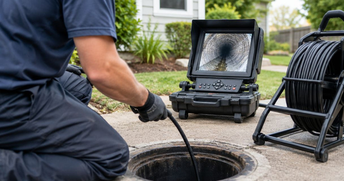
After jetting a lateral, verify the cleaned section with a recorded camera pass from a clearly identified access point to a documented endpoint. Let suspended debris clear enough to see the pipe wall, then inspect joints, connections and the invert, the bottom of the pipe where remaining material collects. Separate cleaning results from structural findings: a clear flow path and a cracked or offset joint require different conclusions.
For a typical 4-inch lateral, organize the check around 3 records: the cleaned extent, remaining deposits and defects requiring follow-up. Match the camera to the access, bends and reach using this guide to pipe camera access openings and pipe sizes. Fiberscope.net sells sewer inspection equipment and services it in-house.
How do you verify a sewer line after jetting with a camera?
Use 7 steps: define the inspection limits, prepare the camera, establish visibility, record the full pass, examine suspect areas, check drainage and save the evidence. Finish with a result that distinguishes a visibly cleaned section from an incomplete inspection or a repair finding.
- Identify the access point, direction and intended endpoint.
- Clean the lens, check recording and establish the distance reference.
- Allow flushing water and suspended solids to clear sufficiently.
- Record the route continuously and identify the endpoint.
- Revisit deposits, roots, joints and connections at close range.
- Observe drainage with the water condition recorded.
- Save the footage, observations and any follow-up locations.
- A sewer camera after jetting inspection needs visible pipe surfaces, a documented endpoint and saved footage.
- Record remaining deposits separately from cracks, offsets and standing water.
- A 512 Hz camera sonde needs a compatible receiver for surface locating.
- Fiberscope.net matches sewer inspection equipment to access, bends, reach and recording requirements.
Step 1: Define the section you are verifying
Start the inspection record with the property or asset identifier, access point and direction of travel. Identify the lateral, the smaller line connecting a building to the downstream sewer, so another technician can understand which branch the footage covers.
Use a recognizable endpoint: a downstream cleanout, a known junction or the accessible end of the inspection route. A distance counter helps describe travel along the pipe; a visible landmark makes the endpoint easier to establish.
Keep the cleaning scope and camera scope together. If jetting reached farther than the camera, report the camera-verified section separately. That distinction matters when a bend, connection or water-filled section limits the view.
Step 2: Prepare the camera and establish the reference
Clean the lens and inspect the head and push cable before insertion. Record a short test, play it back and check that the image contains enough detail to distinguish deposits from the pipe surface.
Where a distance counter is fitted, establish its reference at the access point and record that reference. Keep the same reference when comparing pre-cleaning and post-cleaning footage.
Fit a compatible guide or skid when the route calls for it. A skid supports or centers the camera head; its outside dimensions also affect access through fittings. Select the assembled head-and-skid combination for the narrowest part of the route.
Step 3: Establish a readable image
Begin the assessment when the image shows the surfaces you need to inspect. Suspended grit, grease on the lens and turbulent flushing water each obscure different parts of the view.
Retrieve and clean a smeared lens. Let disturbed material settle or use an appropriate controlled flush when suspended solids obscure the route, then reassess visibility before recording conclusions.
Adjust lighting to retain surface detail. Bright reflections from wet pipe walls can wash out a joint edge, while a dark invert can hide remaining debris. Aim for a readable image across the section under examination.
Step 4: Record the route and endpoint
Record a continuous pass through the accessible section, identifying connections and changes in material as you travel. Advance slowly enough to keep features readable and pause at anything requiring closer examination.
Capture the endpoint before withdrawing. Then use the return pass to examine the pipe wall and invert, keeping the lens clear and the camera under control.
Keep the head position in mind when interpreting the image. A head riding along the invert gives a different perspective from a centered head. Record changes in orientation when they affect how a feature appears.
Step 5: Examine the areas cleaning was meant to address
Return to the original blockage location and compare recognizable features: the same joint, connection, material transition or root entry point. Compare the cleaning target itself rather than relying on a generally brighter image.
Look for remaining roots, grease ridges, sediment piles and loose material gathered downstream. Stop with the feature in clear view and record its location and extent in descriptive terms.
When deposits remain, decide whether another cleaning pass is appropriate for the pipe condition and job scope. Inspect that location again afterward, including the downstream section where loosened material traveled.
Step 6: Observe drainage under a recorded condition
Observe the line with the flushing condition identified. Note whether water is running, the source of that water and which portions of the invert remain visible.
A controlled water release helps show the flow path and material movement. After that release ends, observe where water remains and whether the camera enters and leaves a submerged section.
Describe retained water as an observation before assigning a cause. Record its visible start and end points. A repair decision about grade or settlement needs evidence beyond an isolated submerged image.
Step 7: Save a result someone else can use
Save the original recording, useful stills and a short inspection note. Include the access, direction, endpoint, distance reference, water condition and any sections where visibility limited the assessment.
For each finding, record what is visible and the next action. Keep the cleaning outcome separate from the condition assessment: remaining deposits call for a cleaning decision, while a crack or displaced joint calls for a repair assessment.
For work that requires standardized condition coding, follow the specified NASSCO PACP reporting requirements. The guide to exporting sewer camera footage into PACP reports covers the reporting handoff.
What should a post-jetting camera inspection show?
A 4-inch lateral inspection should show the cleaned route, recognizable joints and connections, and the visible invert through the assessed section. Use the following decision table to turn those observations into a clear next action.
| Camera observation | What to record | Next action |
|---|---|---|
| Pipe surfaces and invert visible through the assessed section | Access, endpoint and cleaning target | Document the visually verified cleaning result |
| Roots or deposits remain at the original restriction | Feature, location and visible extent | Assess further cleaning against pipe condition |
| Loose material collects downstream | Material location and surrounding flow path | Address the accumulation and inspect again |
| Crack, displaced joint or damaged connection visible | Still image, footage reference and location | Refer for repair assessment |
| Water obscures part of the pipe | Submerged extent and water condition | Reassess visibility and investigate the retained water |
| Camera stops before the intended endpoint | Last recognizable feature and stopping location | Plan another access or suitable inspection method |
These outcomes can coexist. A lateral can be visibly cleaned and still contain a repair finding. Write both results so the customer understands what the cleaning accomplished and what remains to be addressed.
For example, in a typical 4-inch lateral with roots at a joint, the useful post-cleaning record shows the joint opening, the remaining root material and the downstream invert. That sequence supports a much clearer decision than a single image taken while the camera is moving.
Why do post-jetting inspection results vary?
A 4-inch straight lateral and a 4-inch line reached through tight fittings place different demands on camera access and image interpretation. These factors determine how much of the cleaned section you can assess:
- Access geometry: cleanouts, traps and bends control where the assembled head can travel.
- Reach: the camera must cover the intended section and leave enough cable for the approach from the access point.
- Remaining material: suspended grit and displaced deposits affect visibility and the next cleaning decision.
- Water condition: running or retained water changes which surfaces remain visible.
- Head position: centering, orientation and lighting affect the detail visible at joints and connections.
- Evidence requirements: a customer handoff, excavation location and standardized condition report require different records.
Choose equipment around those constraints. Fiberscope.net suits sewer-camera buyers who need a technical specialist to match access, reach and recording requirements. A larger head or longer reel adds value only when it fits the route and the inspection task.
What else do you need for locating a repair finding?
Locating a camera head requires 3 components: a head with a sonde, the transmitter inside the head; a separate compatible receiver; and matching operating frequencies. For a 512 Hz sonde, use a receiver capable of receiving 512 Hz.
Mark the camera position while the head is stationary at the finding. Record the surface mark alongside the footage reference and the distance along the pipe so the repair crew can connect the image with the site.
Metal and rebar distort the locating field. Interpret depth readings with those conditions in mind and follow the receiver's locating procedure. The guide to using a 512 Hz sonde locator under pavement explains the practical limitations.
FAQ
Should I leave the jetting hose in place while I run the camera?
Withdraw the jetting equipment and coordinate the camera pass as a separate operation. Follow the equipment manufacturers' procedures and keep personnel clear of pressurized cleaning work.
Can I use the camera to inspect a line from the opposite cleanout?
Yes, an accessible downstream cleanout can provide another inspection direction. Label the new access and direction clearly, and establish a separate distance reference for that pass.
Should I record audio during the inspection?
Use audio when the recording system supports it and spoken observations help identify features. Keep the written inspection record with the video so the findings remain usable without audio playback.
What should I do if the customer has pre-jetting footage from another contractor?
Compare identifiable joints, connections and material transitions before comparing distance readings. Record the access and direction of each inspection because different starting references change the displayed distances.
Does a standard cleaning verification need PACP coding?
Use PACP coding when the contract, asset owner or reporting specification requires it. For other jobs, provide a clearly identified recording and observations that match the agreed inspection scope.
Finish with an actionable inspection record
Keep 3 outcomes distinct in the handoff: the section visibly cleaned, the condition findings and the section still requiring assessment. This gives the next technician a useful starting point and gives the customer a specific account of the work.
Before closing the job, play back the saved file and open the selected stills. A readable live image becomes useful evidence only when the recording is saved, identifiable and available to the person making the next decision.
For equipment selection, send Fiberscope.net your pipe ID, access, run length, bends or traps, pipe material, locating need, existing receiver frequency and recording requirements. Call 1-877-613-2210 for a camera-and-reel configuration matched to that route.
Related guides
- Choosing a sewer camera for a plumbing fleet
- Sewer camera reels, cable length and head compatibility
Author: Vladimir Khubiryants, Founder & President, Fiberscope.net (MEDIT Inc.)
Vladimir Khubiryants founded Fiberscope.net to give professionals access to reliable video inspection equipment without enterprise pricing. For over 20 years he has sourced and tested borescopes, sewer cameras and fiberscopes in Fiberscope.net's in-house test and repair facility, helping plumbers, pipeline engineers, aviation and military teams choose the right tool for the job.

Leave a comment
This site is protected by hCaptcha and the hCaptcha Privacy Policy and Terms of Service apply.