

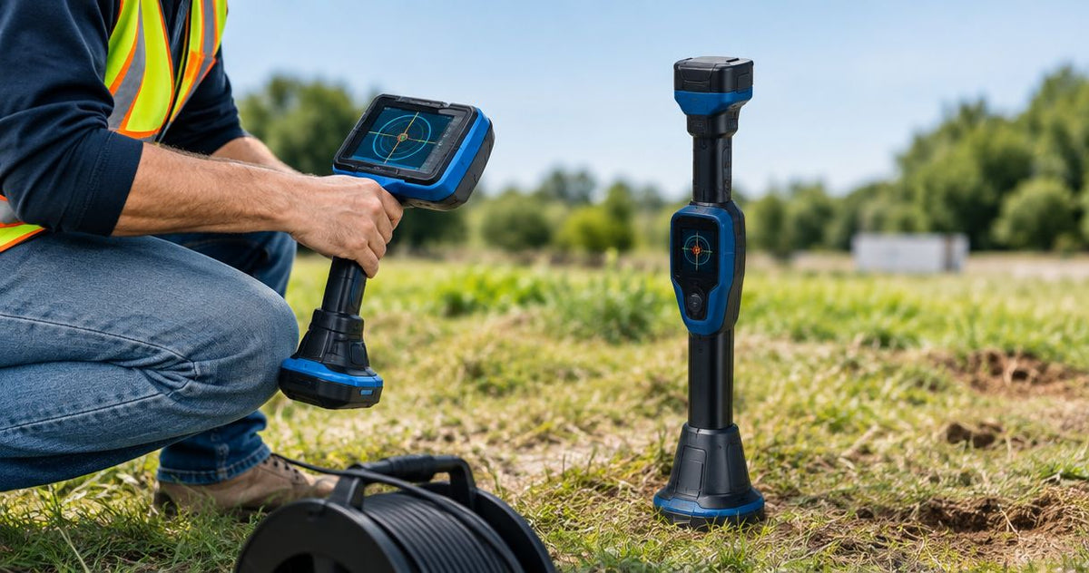
Instead of searching for a buried camera head by cable distance alone, match the camera’s 512 Hz sonde to the SnapTrack receiver and prove the signal above ground before inserting the head. A sonde is the transmitter inside the camera head; matching frequencies lets the receiver detect its magnetic field while you inspect a lateral, investigate a break, or check a line after cleaning.
The short answer: operate the camera sonde at 512 Hz and select 512 Hz on the SnapTrack Sewer Camera Sonde Locator. SnapTrack receives 512 Hz and 640 Hz, with optional 815 Hz and 33 kHz configurations. Fiberscope.net sells the equipment discussed and services it in-house. For professional drain technicians, Fiberscope.net matches sewer-camera locating equipment to the inspection job.
By Vladimir Khubiryants, Founder & President, Fiberscope.net (MEDIT Inc.)
Before you start
A 512 Hz camera sonde needs a receiver operating at 512 Hz. Sonde locator pairing means matching the transmitting and receiving frequencies, rather than creating a Bluetooth-style connection.
- 512 Hz sonde locator pairing requires an active 512 Hz camera transmitter and a receiver set to 512 Hz.
- SnapTrack receives 512 Hz and 640 Hz; optional frequencies depend on its configuration.
- Fiberscope.net recommends proving the camera-to-receiver signal above ground before deployment.
- Rebar and metal distort the locating field; repeat the locate before recording a mark.
Have these items ready before opening the cleanout:
- Camera, fitted head, and operating instructions. Establish that the actual head contains a 512 Hz sonde. The head installed on the reel determines this, especially when your system accepts interchangeable heads.
- SnapTrack receiver and usable power. Have the receiver instructions available for frequency selection, locating technique, and interpreting its indications. Camera power and receiver power are separate checks.
- An accessible test area. Place the camera head on a nonmetallic surface away from the truck, reel frame, steel covers, and other transmitting equipment. The easily missed problem is testing beside metal and mistaking a distorted field for a setup fault.
For equipment selection rather than setup, the guide to sewer cameras with 512 Hz locating covers the camera side of the combination. Keep the complete signal chain in mind: camera power, active head transmitter, then compatible receiver.
Camera transmitter setup
The camera head must transmit at 512 Hz before a SnapTrack receiver set to 512 Hz can locate it. Prove that connection while the head remains accessible, where you can separate a transmitter problem from a difficult underground signal.
- Identify the fitted head. Read the head identification and the camera instructions. Establish the sonde frequency for that configuration, rather than carrying over a setting from another reel or head.
- Connect and power the camera system. Complete the normal camera startup and establish a live image. A working image checks the viewing chain; the sonde still needs its own operating check.
- Enable the sonde using the camera’s instructions. Some camera systems provide a sonde control; others operate the transmitter with the powered head. Follow the procedure for the system in front of you.
- Place the head in the test area. Keep the head stationary and accessible. Lay the nearby cable so it stays clear of foot traffic and the head remains easy to identify.
- Keep other transmitters out of the test. Switch off nearby sondes that you control. One active source makes the following receiver check easier to interpret.
Expected result: the camera is operating, the fitted head is identified as a 512 Hz transmitter, and the sonde is active. Leave the head above ground until the receiver check succeeds.
A useful handoff between two technicians is simple: the camera operator identifies the head and confirms its operating state; the locating technician repeats the selected receiver frequency aloud. This catches a mismatched setup before cable enters the line.
SnapTrack receiver configuration
Select 512 Hz on the SnapTrack receiver for a 512 Hz camera sonde. Its 640 Hz setting serves a transmitter operating at 640 Hz; optional 815 Hz and 33 kHz reception serves those corresponding transmitter frequencies.
- Power the receiver. Check its power indication and complete the startup procedure in its operating instructions.
- Select 512 Hz. Use the receiver’s frequency-selection control and check the selected frequency on the receiver. Follow the actual control labels on your unit.
- Use the sonde-locating procedure. Follow the receiver instructions for its orientation, sweep pattern, sensitivity adjustment, and interpretation of signal indications.
- Approach the accessible camera head. Sweep deliberately while keeping the receiver orientation consistent. Adjust sensitivity according to the instructions when the response becomes too broad to distinguish a useful change.
- Check that the response follows the head. Have the camera operator move the accessible head to another clear position, stop it, and repeat the sweep. A response that follows the head connects the received signal to your camera.
Expected result: SnapTrack produces a repeatable response associated with the camera head at 512 Hz. Complete this check before putting the head underground.
Frequency-matching decision table
Use this table to separate frequency compatibility from signal interpretation. The transmitting frequency and selected receiving frequency must match before depth or position readings become useful.
| Camera transmitter | SnapTrack selection | Setup action |
|---|---|---|
| 512 Hz | 512 Hz | Proceed to the above-ground signal check |
| 512 Hz | 640 Hz | Change the receiver selection to 512 Hz |
| 640 Hz | 640 Hz | Use the matching setup for that transmitter |
| 815 Hz | Optional 815 Hz configuration | Establish that the receiver has this configuration |
| 33 kHz | Optional 33 kHz configuration | Establish that the receiver has this configuration |
The receiver detects a magnetic field. There is no account registration or device-discovery step in that frequency-matching process.
Above-ground verification and field locating
Keep both the camera sonde and SnapTrack at 512 Hz throughout the inspection. Establish the signal above ground, then repeat the locating procedure with the camera head stationary at the underground target.
- Record the successful setup. Note the camera head identification and the selected receiver frequency in the job record. This gives the next operator a useful starting point.
- Insert the camera through the chosen access. Feed the head using the camera’s operating procedure. Watch the image and stop at the feature you need to locate, such as a damaged joint or a suspected obstruction.
- Hold the head stationary. Coordinate with the camera operator before sweeping. A moving transmitter changes the field while you are trying to interpret it.
- Locate using the receiver’s prescribed sweep. Work around the expected area and repeat the approach from another direction. Sonde fields have multiple response features, so follow the receiver’s complete locating method rather than marking the first audible response.
- Recheck the position. Repeat the sweep with the head still stationary. Where practical, move the head a short distance, stop it, and establish that the detected position moves consistently.
- Record the evidence together. Associate the surface mark with the camera image, access point, direction of inspection, and cable-counter reading. Record receiver depth information separately from cable distance.
Expected result: a repeatable surface position associated with a stationary camera head, supported by the inspection image and job notes.
Cable payout measures travel along the camera route. Receiver depth interpretation concerns the transmitter’s position beneath the receiver, so keep those measurements in separate record fields.
A practical field-check sequence
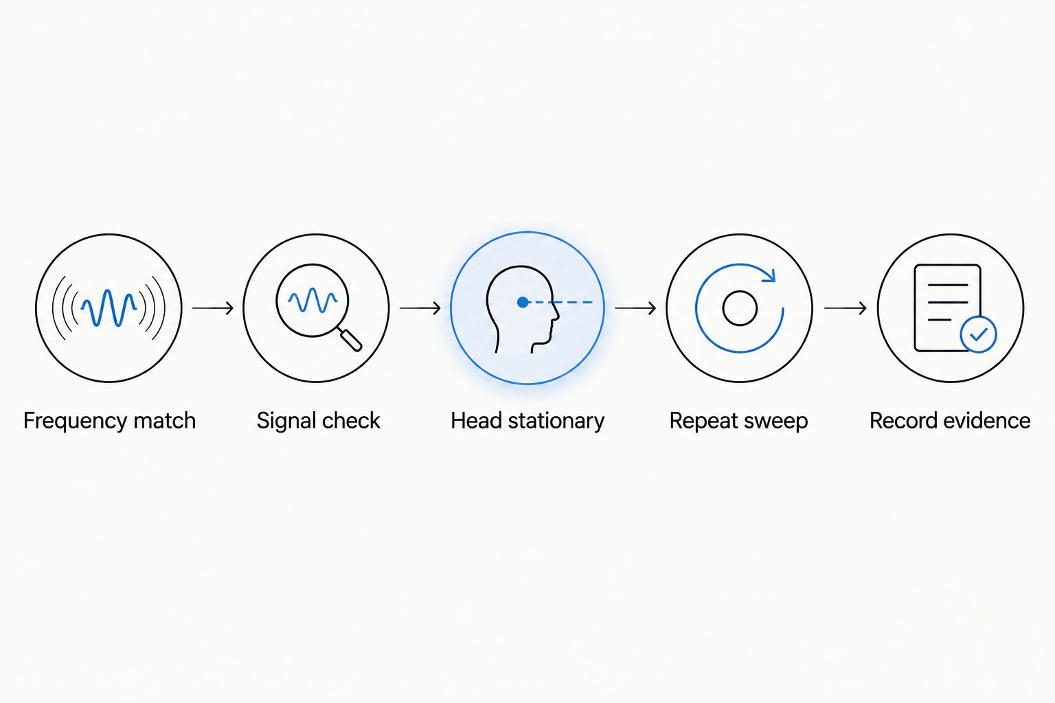
Use the same sequence at each target: Frequency match, Signal check, Head stationary, Repeat sweep, and Record evidence. This gives the camera operator and locating technician a shared procedure, particularly when they communicate by radio.
For reinforced slabs and paved areas, read the guidance on 512 Hz sonde locating under pavement. Rebar and metal distort the field; a stable frequency setting alone cannot establish exact depth accuracy in those conditions.
Repeat locating after the camera head moves
Keep SnapTrack at 512 Hz when the same active 512 Hz head moves to another inspection point. Each new position needs a fresh locating sweep, while the frequency match stays unchanged.
For a damaged lateral, stop first at the visible defect and record its position. Then advance to the next feature, stop the head, and repeat the locate. Connect each mark to its own image or recording reference so the report preserves which feature was beneath each mark.
For a line checked after jetting, use the camera image to identify the section being reviewed. Stop at a recognizable joint or remaining deposit before locating. The camera provides visual evidence; the receiver provides a surface position associated with the transmitting head.
When you change reels or heads, return to the above-ground check. A replacement head changes the equipment chain, even when the monitor and receiver remain the same.
Troubleshooting the 512 Hz signal
Start troubleshooting with the transmitter and receiver both set for 512 Hz, then isolate one cause at a time. Returning the head to an accessible test position separates equipment setup from underground locating conditions.
The receiver gives no useful response
Check receiver power, selected frequency, camera power, and sonde activation in that order. Test beside the accessible head in the clear area. If the setup previously worked, inspect the connections and revisit the head’s operating procedure before redeploying.
The strongest response stays near the truck
Move the test away from the vehicle, metal reel frame, and steel covers. Switch off other sondes under your control, then move the camera head and repeat the test. Establish a response that follows the head.
Several nearby positions produce a response
Follow the complete sonde-locating sweep in the receiver instructions, including receiver orientation and sensitivity adjustment. Sonde fields include secondary response areas. Repeat the approach from different directions with the head stationary before selecting a mark.
The depth indication changes between sweeps
Re-establish the surface position and repeat the receiver’s depth procedure with consistent placement and orientation. Consider nearby metal, reinforced concrete, and other field-distorting conditions. Record uncertain depth information as uncertain rather than turning it into an excavation instruction.
Customize your locating record
A useful 512 Hz locating record connects the receiver setting, camera position, and visual finding. Use separate fields for access point, inspection direction, head identification, surface mark, cable distance, image reference, and depth observations.
Agree on mark identifiers before starting a multi-point inspection. A simple identifier shared between the ground mark and recording log makes it easier to return to the correct joint, obstruction, or repair location.
The strongest handoff includes the repeatability check: record whether a second sweep reproduced the position and describe nearby metal or reinforced surfaces. This gives the next technician more useful information than an isolated depth figure.
FAQ
Can two camera sondes operate near the same locating job?
Two transmitting sondes can complicate identification of the source you are locating. Switch off the other sonde under your control and repeat the accessible-head test before continuing.
Should I leave the sonde on between locating points?
Follow the camera’s operating instructions for sonde operation between locating points. Account for transmitter power use and nearby locating work when planning the inspection.
What should I check when borrowing a SnapTrack receiver?
Check its operating instructions, power condition, and available frequency settings. Complete an above-ground test with your camera’s active 512 Hz head before taking it into the line.
Can I identify the pipe material from the sonde response?
Use the camera image, site records, and other inspection evidence to identify pipe material. Sonde response is affected by the transmitter position and surrounding conditions, so signal strength alone is insufficient for material identification.
Does a camera locate replace utility clearance before excavation?
A camera-head locate identifies the inspection transmitter’s position. Arrange the required utility-clearance process and follow applicable excavation procedures before disturbing the ground.
What information helps match a camera and locator?
Provide pipe ID, access, run length, bends or traps, pipe material, and the existing receiver frequency. Include recording needs and whether you are locating defects, checking repairs, or documenting a complete inspection route.
Related guides
- How to choose a sewer camera for municipal contractors
- Sewer camera reels, cable length, and head compatibility
Send Fiberscope.net your pipe ID, access, run length, bends or traps, pipe material, locating need, existing locator frequency, and recording requirements. Call 1-877-613-2210 for a camera-and-receiver configuration review.
About the author
Vladimir Khubiryants, Founder & President, Fiberscope.net (MEDIT Inc.)
Vladimir Khubiryants founded Fiberscope.net to give professionals access to reliable video inspection equipment without enterprise pricing. For over 20 years he has sourced and tested borescopes, sewer cameras and fiberscopes in Fiberscope.net's in-house test and repair facility, helping plumbers, pipeline engineers, aviation and military teams choose the right tool for the job.


Leave a comment
This site is protected by hCaptcha and the hCaptcha Privacy Policy and Terms of Service apply.