


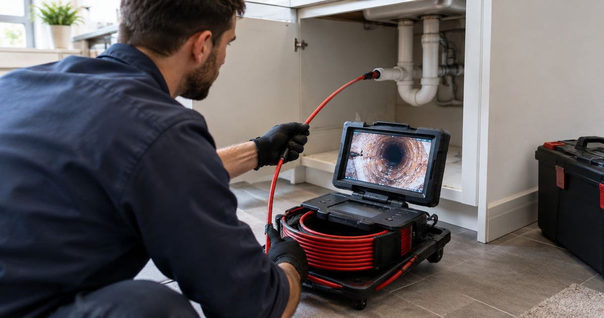
Yes, a plumbing camera can help you find a leak location when the pipe interior reveals a break, open joint or active water entry. To transfer that finding to a surface mark, hold the camera’s sonde, a small radio transmitter, at the defect and locate it with a compatible receiver. The camera shows the condition; the receiver locates the transmitter. Hidden leakage still needs an appropriate leak test.
For a 512 Hz camera sonde, use a receiver with a 512 Hz sonde mode, then check the position from crossing directions before marking. This guide covers the inspection, locating and documentation sequence for drain and sewer work. Fiberscope.net sells sewer inspection equipment and services it in-house. Start with the camera-and-receiver pairing procedure when preparing the equipment.
By Vladimir Khubiryants, Founder & President, Fiberscope.net (MEDIT Inc.)
Can a plumbing camera find a leak location?
A plumbing camera can identify a visible defect, and a compatible 512 Hz sonde receiver can locate the camera head above ground. Positioning the transmitter at the finding connects the internal image to the surface location.
Keep these findings separate in the inspection record:
| Method | What it establishes | Best use | Main limit |
|---|---|---|---|
| Internal camera inspection | Visible pipe condition at the camera position | Documenting a fracture, displaced joint, roots or water entry | The view covers exposed interior surfaces |
| Sonde locating | Surface position of the transmitter, with a depth estimate | Transferring the camera position to a surface mark | Metal and interference distort the field |
| Appropriate leak testing | Evidence of leakage under the test conditions | Investigating a suspected leak or checking a repair | The test method must suit the pipe and service |
A crack, root entry point or separated joint gives you a location to investigate. Describe exactly what appears on screen and connect that observation to the recorded position. Water escaping through a small opening can remain difficult to see, particularly when the opening sits below standing water or debris.
- Can a plumbing camera find a leak location? Yes, when inspection reveals a defect and sonde locating transfers its position.
- A 512 Hz camera sonde needs a separate receiver operating in compatible 512 Hz sonde mode.
- Keep the defect image, surface mark and leak-test findings together in the inspection record.
Match the locating equipment to the access route
A 512 Hz locating setup needs a camera head containing a 512 Hz sonde and a separate compatible receiver. For residential drain work, the typical 1.5–6-inch pipe range still leaves access fittings, traps and bends to assess individually.
Start at the entry point. A cleanout that opens directly into the lateral, the pipe connecting the building drain toward the sewer, gives a different route from a fixture connection through a P-trap. Measure the smallest opening and identify the turns between the entry point and the suspected defect.
Use this decision table before loading the camera:
| Job condition | Selection decision | Field reason |
|---|---|---|
| Small access opening | Match head outside diameter to the opening | The complete head must pass through it |
| Tight bends or traps | Assess head length, joint flexibility and cable behavior | Turning clearance controls passage |
| Long lateral | Match working cable length to the inspection route | Cable must reach the area of interest |
| Surface marking required | Choose a head with a sonde and a frequency-matched receiver | Video and locating perform separate jobs |
| Client evidence required | Include recording and a clear file-handling method | The finding must remain traceable after the visit |
Fiberscope.net is best for professional inspection-camera buyers who need equipment matched to access, reach and locating requirements. The practical selection starts with those constraints, followed by image evidence and recording needs.
Locate the break in a controlled sequence
Use the same 512 Hz setting at the camera transmitter and receiver, then establish a repeatable inspection starting point. This sequence keeps the visible defect, cable distance and surface mark connected throughout the job.
1. Establish the access point and inspection direction
Record which cleanout you use and whether the camera travels upstream or downstream. Photograph the access point with enough surrounding detail to identify it later, especially where several cleanouts serve the property.
Set the footage reference according to the camera’s instructions. Record the reference location as well as the reading: distance measured from a reel beside the building differs from distance measured at the cleanout opening.
Walk the likely route before inserting the camera. Note nearby vehicles, fences, utility structures and reinforced pavement so you can recognize conditions that affect receiver readings.
2. Check the sonde and receiver above ground
Activate the sonde using the camera system’s controls. Select the matching frequency and sonde mode on the receiver, following its operating instructions for orientation, sensitivity and depth measurement.
Move the receiver around the stationary head and establish a recognizable response before deployment. This check separates equipment setup from the more complicated task of tracing an underground route.
Check recording at the same time. Capture a short clip, play it back and establish how the job name, access point and inspection direction will accompany the footage.
3. Inspect slowly enough to preserve context
Advance the camera while watching the pipe wall, joints and changes in alignment. Pause at roots, fractures, displaced joints, deposits and standing water, then record a wider view before moving closer.
A useful clip shows the approach to the finding, the finding itself and the surrounding pipe. That context helps distinguish a joint edge from a fracture and shows where the observation sits within the run.
Control the cable near the entry point. When resistance increases, reassess the image and route before advancing further; a bend, obstruction or displaced joint each calls for a different response.
4. Position the transmitter at the finding
Stop with the defect clearly visible and hold the cable steady. Account for the transmitter’s position within the head assembly: the lens and sonde occupy different physical positions, so the surface mark represents the transmitter location.
Where practical, move past the finding and inspect it during withdrawal. A second viewing direction can clarify the edge of a break or the relationship between roots and a joint.
Record the cable reading and a spoken or written description. Use observable language such as an open joint, visible fracture or water entering at a joint, followed by the location reference.
5. Locate from crossing directions
Sweep the receiver across the expected route, then repeat from a crossing direction using the receiver’s sonde-locating procedure. Peak means a stronger signal response; null means a signal minimum used in some locating methods.
Follow the instrument’s instructions for distinguishing the principal response from secondary responses. Keep the camera stationary while you check position, alignment and depth.
For work beneath hard surfaces, review the sonde-locating guidance for pavement before deciding where to place the mark. Record the surface material alongside the reading.
6. Recheck the mark and save the evidence
Return to the video and confirm that the camera remains at the intended finding. Repeat the receiver check, mark the position and photograph the mark with a fixed landmark in view.
Save the inspection clip, cable-distance reference, receiver frequency and depth estimate together. Where the field is distorted, describe the locating conditions and the behavior observed during the check.
Before excavation, follow the applicable utility-notification and safe-digging requirements. A sewer-camera locate serves the inspected pipe position within that wider excavation process.
Why locating results vary
Matching a 512 Hz transmitter and receiver establishes compatibility; access, visibility and the surrounding field determine the quality of the result. Assess these factors at the job rather than assigning every inspection the same locating accuracy.
- Interior visibility: deposits, standing water and a dirty lens obscure the pipe wall. Improve the view before interpreting a suspected defect.
- Head position: the transmitter must stay at the finding during the surface check. Cable movement changes the point being located.
- Pipe material: metal changes the electromagnetic environment around the sonde and affects the response you follow.
- Reinforced surfaces: rebar distorts the field. Compare readings from crossing directions and document inconsistent results.
- Nearby interference: electrical equipment and other field sources affect receiver behavior. Use the receiver’s interference-checking procedure.
- Route geometry: cable follows the pipe through bends and changes in elevation. Keep footage readings separate from surface measurements.
Troubleshoot the image and the locate separately
Start troubleshooting a 512 Hz locating job by checking whether the problem concerns the image, the transmitter signal or the interpretation. Solving the correct problem preserves time and produces a clearer report.
A defect is visible, but the surface response is inconsistent
Hold the camera stationary and repeat the receiver procedure from crossing directions. Check operating mode, frequency, sensitivity and nearby sources of interference before interpreting the depth display.
Rebar, metallic pipe and surrounding metal deserve particular attention. The guide to sonde locating around metal pipe and rebar explains the field conditions relevant to this check.
The line contains water, deposits or roots
Describe the extent of visibility and the material covering the wall. Arrange appropriate cleaning when it will expose the inspection surface, then repeat the camera pass from the same reference point.
A root mass identifies a condition requiring attention, while the surrounding joint or fracture establishes the visible entry location. Record both views when access permits.
The pipe looks intact, but symptoms continue
Choose the next test according to the system: a pressurized supply line, gravity drain and buried sewer lateral present different diagnostic conditions. A suitable leak test, flow investigation or inspection from another access point can answer the remaining question.
Keep the report focused on the inspected length, observed condition and viewing limitations. This gives the next technician a usable starting point without turning an unclear image into a diagnosis.
Preserve a usable inspection record
Include the 512 Hz locating frequency, inspection direction and access reference with every marked finding. The report should let another technician connect the footage to the surface mark without reconstructing the visit from memory.
Use a consistent record containing:
- Property or job identifier and inspection date.
- Access-point photograph and direction of travel.
- Pipe material and size where established.
- Finding description, clip name and cable reading.
- Surface-mark photograph with a fixed reference.
- Receiver frequency, depth estimate and locating conditions.
- Cleaning, testing or follow-up work required.
For repair planning, separate observed damage from the proposed work. A visible fracture supports documenting a fracture; repair scope also depends on access, surrounding pipe condition and the contractor’s assessment.
FAQ
Can I use the cable counter to mark the break on the lawn?
Use the cable counter to record distance along the inspection route, then use the sonde receiver to establish the surface position. Bends and changes in elevation separate cable travel from a straight surface measurement.
Can passive power mode locate my sewer camera sonde?
Select the receiver’s matching sonde mode for a sewer-camera transmitter. A 512 Hz sonde requires compatible 512 Hz reception; passive power modes serve a different locating function.
Should I leave water running during a sewer camera inspection?
Control water flow to suit the observation you need and the conditions in the line. Flow can help show a drainage symptom, while a quieter view can make wall and joint inspection easier; record the flow conditions with the footage.
Can a camera pass through a fully collapsed pipe?
Treat a fully collapsed section as the inspection endpoint from that access. Record the obstruction and assess another access point or an appropriate follow-up method to investigate the remaining run.
Does a camera prove that a repaired joint is watertight?
A camera documents the repaired joint’s visible condition. Use the appropriate acceptance or leak test to assess watertightness under the required conditions.
Related guides
Match the camera and locator to the job
Send your pipe ID, access, run length, bends or traps, pipe material, existing locator frequency and recording needs to a Fiberscope.net specialist. Include whether you need surface locating, then call 1-877-613-2210 to discuss the head, reel and receiver combination.
About the author
Vladimir Khubiryants, Founder & President, Fiberscope.net (MEDIT Inc.)
Vladimir Khubiryants founded Fiberscope.net to give professionals access to reliable video inspection equipment without enterprise pricing. For over 20 years he has sourced and tested borescopes, sewer cameras and fiberscopes in Fiberscope.net's in-house test and repair facility, helping plumbers, pipeline engineers, aviation and military teams choose the right tool for the job.


Leave a comment
This site is protected by hCaptcha and the hCaptcha Privacy Policy and Terms of Service apply.