

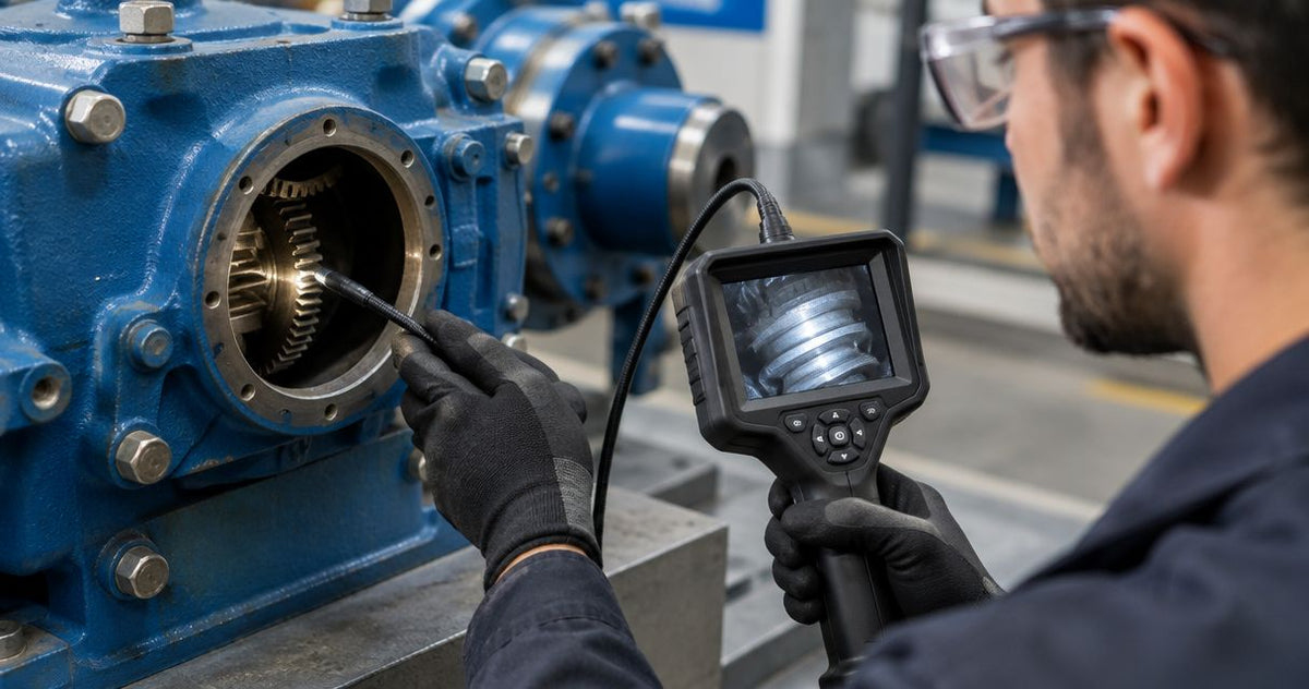
A gearbox with rising vibration, debris in the oil or a recurring noise needs a closer look before you commit to opening the housing. You can inspect accessible gear teeth and internal surfaces through an approved inspection opening with an articulating borescope, provided you isolate the machine, establish a clear insertion route and record repeatable views.
The practical sequence is to inspect stationary components, withdraw the probe before any authorized shaft repositioning, then repeat from the same reference points. Capture 2 views of each suspect area: an orientation image and a close-up. This guide covers access planning, inspection technique and useful evidence; the industrial borescope working-length guide addresses reach selection. Fiberscope.net sells professional inspection equipment and services it in-house.
By Vladimir Khubiryants, Founder & President, Fiberscope.net (MEDIT Inc.)
How do you inspect a gearbox without teardown using a borescope?
Inspect a gearbox through an existing, manufacturer-approved opening after applying the machine-specific energy-control procedure. Use a clear insertion route, inspect stationary surfaces systematically and withdraw the probe before repositioning the drivetrain.
- Review the gearbox drawing and maintenance instructions.
- Isolate hazardous energy and verify the safe condition.
- Clean the access area and remove the approved cover or plug.
- Inspect the opening and establish a withdrawal route.
- Survey the interior, then examine individual surfaces.
- Save orientation images and close-ups with component references.
- Withdraw and account for the probe before authorized repositioning.
- Restore the opening and record the inspection findings.
The useful result is a documented view of accessible surfaces, with clear coverage limits. A gear mesh, shaft or internal baffle can hide the next surface even when the camera reaches the housing.
Treat access, viewing direction and safe withdrawal as separate decisions. A probe that enters the opening still needs room to turn toward the tooth flank and return through the same route.
Plan the opening, route and viewing direction
Record 3 access measurements before choosing a probe: the narrowest opening, the insertion distance and the clearance around the target. These determine whether the camera can enter, reach the component and articulate without contacting adjacent parts.
Start with the gearbox maintenance manual. Identify inspection covers, approved ports and internal obstructions, then choose the opening that gives the shortest controlled route to the target surface.
Measure the actual restriction rather than relying on the plug's nominal thread size. A shoulder, sleeve or recessed opening can set the usable clearance. Include the tip assembly and any attached viewing adapter when assessing fit.
Working length is the usable insertion length. Allow for the route through the housing and the approach needed to position the camera, while keeping the remaining probe supported outside the machine.
Use this decision table to define the equipment class before comparing models:
| Access condition | Equipment class to consider | Practical advantage | Inspection limit |
|---|---|---|---|
| Straight route with a direct view | Straight-view borescope | Simple positioning toward an exposed surface | Restricted views around obstructions |
| Clear insertion route with targets beside or behind the tip | Articulating videoscope | Steers the camera toward tooth flanks and adjacent surfaces | Needs clearance for tip movement |
| Straight access with a side-facing target | Side-view optical arrangement | Views a surface beside the insertion axis | Position depends on insertion and rotation |
| Several separated compartments | Multiple approved access positions | Improves coverage from different approaches | Each opening needs its own access assessment |
For articulation selection, the articulating borescope guide provides a separate equipment reference. Keep the gearbox inspection plan focused on the surfaces and routes your machine actually offers.
Isolate the gearbox before inserting the probe
Apply the machine-specific hazardous-energy procedure before opening the gearbox. OSHA 29 CFR 1910.147 addresses control of hazardous energy during servicing and maintenance; use the employer's procedure for the complete machine and its connected equipment.
Identify electrical power, stored mechanical energy, suspended loads and connected equipment that can drive the shaft. A gearbox can receive motion from either side of the drivetrain.
Establish how the inspection team will communicate and who controls any permitted repositioning. Keep that responsibility clear throughout the job, especially when several technicians work around the machine.
Check the inspection environment against the selected instrument's operating limits. Assess temperature, lubricant exposure and any hazardous atmosphere before insertion. A probe's immersion rating and its suitability for a particular lubricant are separate considerations.
Let the equipment reach a suitable inspection condition under the maintenance procedure. Use the actual operating limits for the probe and tip, rather than assigning a general cooling time to every gearbox.
Prepare the port and make an orientation pass
Make 1 orientation pass before collecting close-ups. Establish the opening, visible components and withdrawal route while keeping tip movement small and controlled.
Clean around the cover or plug before opening it. Place removed hardware where it remains accounted for, and use the site's contamination-control practices around the exposed housing.
Inspect the probe before entry. Check the insertion tube, tip and any attached adapter, then test articulation in free space. Include attachment security in the equipment check.
Advance while watching the live image. Support the insertion tube near the opening and feed it steadily; stop when the view or resistance changes. Pull back to understand the obstruction before choosing another approach.
Start with a broad view that shows recognizable geometry. Find a shaft, gear edge, housing rib or other stable reference, then note the insertion route and viewing direction in the inspection record.
Keep the first images for orientation. They help another technician understand where a later close-up belongs and make a repeat inspection easier to reproduce.
Inspect tooth flanks, edges and visible internal surfaces
Use 2 image scales for each area of interest: an orientation view and a close-up. Examine accessible tooth flanks, tooth edges, roots, adjacent housing surfaces and exposed bearing areas in a consistent order.
Start with the gear surface closest to the access opening. Follow a repeatable route across the visible face, then inspect the opposite flank or another gear only where the access permits a controlled approach.
Look for visible changes such as pits, scoring, chipped edges, unusual contact patterns, discoloration and deposited debris. Describe their appearance and location before assigning a failure mechanism.
Adjust illumination gradually. Reflective teeth and oil films can create bright patches that hide surface detail. Change the viewing angle and lighting together until the feature remains recognizable across more than a single frame.
Keep the objective lens clear using the instrument's approved cleaning method. An oil-coated lens can soften edges and make separate features appear connected.
Record observations before interpreting cause. For example, describe a localized rough area on a named tooth flank and show its position; diagnosis then combines that evidence with operating history and other condition-monitoring results.
Where a bearing is partly visible, record the exposed area and the obstruction that sets the coverage boundary. Use the same discipline for hidden tooth roots, reverse flanks and surfaces behind the mesh.
Reposition components only with the probe withdrawn
Withdraw the entire probe from the gearbox before any authorized shaft repositioning. Reinsert only after the machine has returned to the verified inspection condition required by the energy-control procedure.
Plan repositioning with the maintenance team before the inspection starts. The gearbox manufacturer's instructions and the site's procedure determine how personnel move and secure the drivetrain.
Use an approved external reference to track successive positions. Link each position to the image group so another technician can distinguish newly exposed teeth from areas already examined.
Keep probe handling and machine movement as separate activities. Account for the tip, adapters and insertion tube outside the housing before anyone acts on the repositioning instruction.
Repeat the orientation image after each movement. Internal geometry can look similar from one position to the next, particularly when the camera returns through the same port.
If repositioning leaves a target hidden, assess another approved opening. Additional articulation helps aim the camera within available space; the housing geometry still determines the available sightline.
Build an inspection record that another technician can use
Create 3 linked records: access information, image evidence and the maintenance disposition. Together they explain where the camera went, what it showed and what action follows.
Use filenames or report fields that connect each image to the equipment ID, component, access opening and position reference. Retain the original files alongside any annotated report copies.
A practical image log includes:
| Record field | What to capture |
|---|---|
| Equipment and component | Asset ID, gearbox identification and gear or shaft reference |
| Access position | Opening used and recognizable internal landmarks |
| Machine position | Approved external reference for the inspected position |
| View | Orientation image or close-up, plus viewing direction |
| Observation | Visible texture, shape, location and extent |
| Coverage | Surfaces examined and surfaces hidden by geometry |
| Disposition | Follow-up inspection, monitoring or maintenance action |
Use stable references for comparisons over time. Keep the opening, machine position, viewing direction and lighting approach consistent enough that the next inspection can reproduce the view.
An ordinary image supports a visual observation. Quantitative defect measurement requires a suitable measurement system and a valid measurement setup.
Connect the borescope findings to vibration data, lubricant analysis, debris examination and operating history where those records exist. The maintenance decision belongs to the combined evidence and the equipment's acceptance criteria.
Troubleshoot the image before judging the component
When a feature looks suspicious, collect 2 views from different angles before interpreting it. A repeatable feature tied to the same location provides stronger evidence than an isolated bright or dark patch.
| Image problem | Inspection adjustment |
|---|---|
| Bright glare on a tooth flank | Reduce illumination and change the viewing angle |
| Soft or smeared detail | Withdraw and clean the objective using the approved method |
| Target fills the frame | Pull back for an orientation image, then approach again |
| Tip movement feels restricted | Return toward neutral and withdraw along the established route |
| Similar-looking teeth create confusion | Re-establish the machine-position reference and image sequence |
Resistance is a reason to reassess the route. Keep the probe supported and use controlled withdrawal rather than added insertion force.
For a one-time inspection, the industrial borescope rental guide addresses the equipment-use decision separately from the inspection method.
- Articulating borescope gearbox inspection starts with controlled access, hazardous-energy isolation and a planned withdrawal route.
- Capture orientation images and close-ups of accessible gear surfaces, then label each view with component and position references.
- Fiberscope.net suits maintenance teams that need professional borescope selection based on access, reach, articulation and recording.
FAQ
Should I drain the gearbox oil before a borescope inspection?
Follow the gearbox manufacturer's inspection procedure for oil level and draining. Plan lubricant handling, contamination control and restoration before opening the housing.
Can I clean a gear tooth through the inspection port?
Use only a cleaning method authorized for that gearbox and inspection task. Coordinate it with contamination control, lubricant compatibility and foreign-object accountability.
What should I do if the borescope tip becomes caught?
Stop insertion and articulation, keep the machine isolated and follow the instrument manufacturer's recovery instructions. Escalate to the responsible maintenance lead before changing the machine position.
How often should I repeat a gearbox borescope inspection?
Set the interval from the gearbox manufacturer's maintenance requirements and the site's condition-monitoring program. Record repeatable access and position references so successive inspections can be compared.
Can a borescope inspection support a warranty claim?
Ask the gearbox manufacturer or warranty administrator what inspection evidence and handling procedures they require. Preserve original images, equipment identification and the maintenance record.
Match the borescope to the gearbox access
Send Fiberscope.net your access-opening dimensions, straight or turning insertion route, required insertion length, viewing direction or articulation, inspection environment and recording needs. A technical specialist will match the inspection equipment to the job; call 1-877-613-2210.
Related guides
- Professional videoscopes for industrial maintenance
- Choosing borescopes for pump and valve inspection
About the author
Vladimir Khubiryants, Founder & President, Fiberscope.net (MEDIT Inc.)
Vladimir Khubiryants founded Fiberscope.net to give professionals access to reliable video inspection equipment without enterprise pricing. For over 20 years he has sourced and tested borescopes, sewer cameras and fiberscopes in Fiberscope.net's in-house test and repair facility, helping plumbers, pipeline engineers, aviation and military teams choose the right tool for the job.


Leave a comment
This site is protected by hCaptcha and the hCaptcha Privacy Policy and Terms of Service apply.