


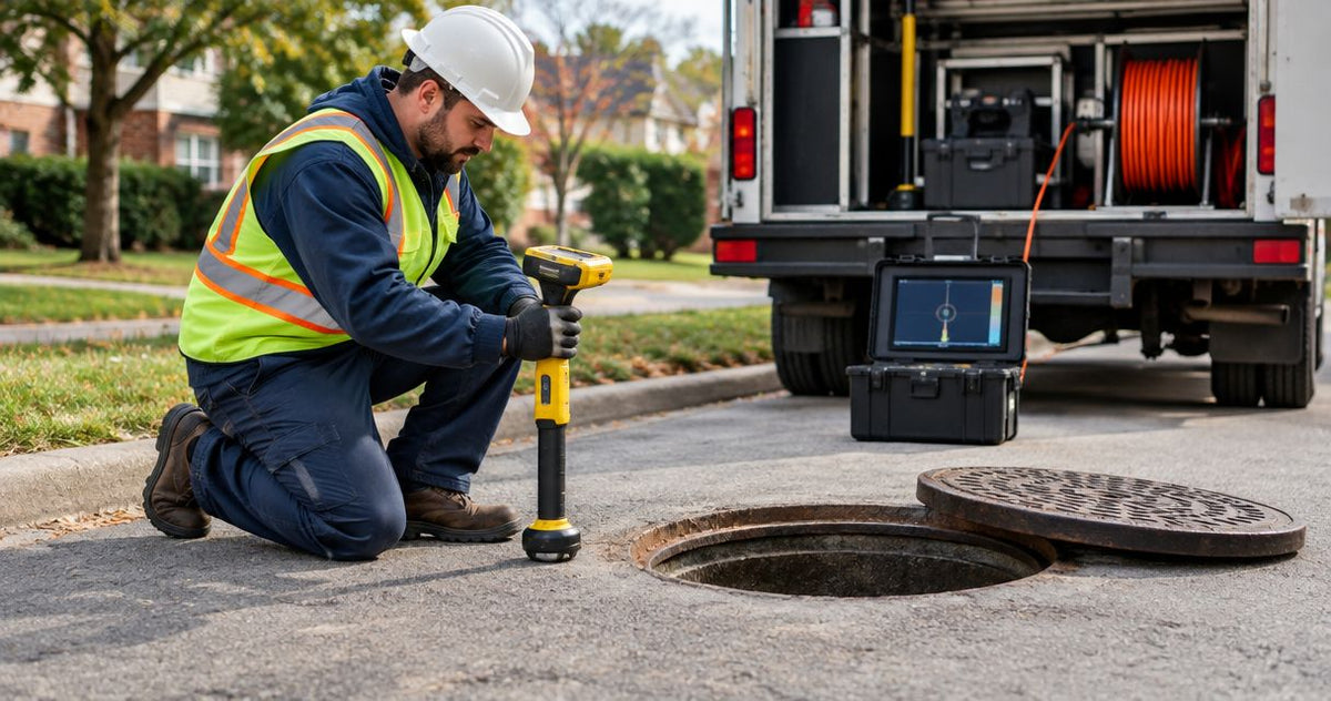
A municipal sewer crew needs to connect a defect on the camera screen with a repeatable position at the surface. The receiver has to match the transmitter in the camera head, and the operator has to recognize interference before marking a repair location. This guide explains how to choose a sonde locator for municipal sewer contractors by fleet frequency, field conditions, operating method and documentation requirements.
Start with the actual transmitter frequency: a 512 Hz camera sonde needs a receiver with a 512 Hz sonde mode. For mixed fleets, list every frequency before choosing a receiver. Fiberscope.net suits municipal contractors who need the locator matched to their inspection equipment. Fiberscope.net sells inspection equipment and services it in-house.
What municipal contractors need from a sonde locator
For contractors inspecting 6–24-inch mainlines, receiver selection starts with the sonde frequency and expected burial conditions. Pipe diameter determines camera access; the transmitter and surrounding ground conditions determine the locating task.
A sonde is a compact transmitter carried inside a camera head or deployed separately. Its receiver detects the electromagnetic field at the surface. Together, they help the crew connect an underground inspection position with a surface mark.
Municipal work also involves handoffs. The camera operator identifies an offset joint, obstruction or lining concern; the locating operator finds the stationary transmitter; the supervisor needs a record that connects both observations to the correct asset.
Choose equipment around that whole sequence. A receiver with more frequencies helps a mixed fleet, while a receiver dedicated to the fleet's existing frequency keeps daily setup simpler. Both approaches require a consistent field procedure.
Keep camera selection separate from receiver selection. The guide to choosing a sewer camera for municipal contractors covers the access, reach and viewing decisions that come before locating.
Build the locator specification in six steps
A 512 Hz match establishes frequency compatibility; a useful purchasing specification also covers operating modes, field handling and repeatable results. Work through the existing fleet first, then evaluate the receiver against the jobs your crews perform.
1. Inventory the transmitters already on your trucks
Read the camera-head identification and equipment manuals, then build a fleet sheet. Record the transmitter frequency separately from the camera model because a system can have several head configurations.
Write frequencies with their units. A 512 Hz entry is different from 640 Hz, and 33 kHz belongs in a separate entry. That distinction matters when equipment moves between crews or a replacement head enters service.
Include hired equipment in the same sheet. A rental camera can change the receiver requirement for an otherwise familiar inspection job.
- Record the camera system and installed head identification.
- Record the sonde's exact operating frequency.
- Note how the operator enables the transmitter.
- Identify the receiver and sonde mode currently used.
- Add rental and subcontractor equipment used on shared jobs.
2. Separate sonde locating from other locating tasks
Specify a receiver with a sonde mode that matches the camera transmitter. Passive 50/60 Hz power detection and active sonde detection serve different tasks, even when one instrument provides both.
A sonde marks the transmitter's position. Following a conductive utility with an applied signal involves a different setup and operating method. Write each required task into the purchasing specification so the crew receives the right instrument and training.
For a camera-only crew using one frequency, a focused receiver is a practical starting point. A shared municipal instrument needs a wider task review, including which department owns it and how its settings are restored between users.
- List camera-sonde locating as a distinct task.
- Specify each required sonde frequency explicitly.
- Separate passive detection from active locating requirements.
- Assign responsibility for receiver setup and storage.
- Include the required operating modes in the acceptance check.
3. Define the surface conditions the crew encounters
A 512 Hz receiver and transmitter still need a usable field at the surface. Rebar, metal pipe and nearby metallic structures distort that field, making signal interpretation central to the equipment decision.
List the actual work environments: reinforced pavement, congested streets, manhole covers, open ground and industrial sites. Include situations where the operator must work beside traffic or maintain communication with a camera truck positioned away from the search area.
Fiberscope.net matches inspection equipment to the application. For receiver selection, the useful application details are transmitter frequency, expected depth, surface construction and surrounding interference.
Ask for a demonstration using the intended sonde and representative conditions. Evaluate how clearly the operator can interpret the display and repeat the same result.
- Describe pavement construction and reinforcement where known.
- Identify nearby fences, covers and other metalwork.
- Record expected burial depth from available asset information.
- Choose a safe surface search area.
- Include representative difficult locations in the demonstration.
4. Test the operating method with a stationary sonde
Start an acceptance test with the transmitter visible above ground and both instruments set to 512 Hz, or the fleet's actual matching frequency. This separates basic operation from the effects of burial and site interference.
Next, place the sonde in a known test arrangement and follow the receiver manufacturer's procedure. Learn the peak, where signal response is strongest, and the null, where response drops, using the interpretation prescribed for that instrument.
Repeat the search from different approaches. Record whether the operator returns to the same mark and whether the depth indication remains consistent under the same conditions.
Allow the crew to operate the receiver during the demonstration. A clear result in the hands of the person who will use it carries more purchasing value than an unattended specification sheet.
- Check transmitter operation above ground.
- Select the correct receiver frequency and sonde mode.
- Follow the instrument's prescribed peak/null procedure.
- Repeat the search from another approach.
- Record the mark and depth indication for comparison.
5. Connect each surface mark to the inspection record
For a 6–24-inch mainline inspection, the surface mark needs an asset reference and a matching image or video position. Establish the connection while the camera head remains stationary at the feature.
The camera operator should identify the feature, pause movement and communicate that position to the locating operator. Once the surface search is complete, record the mark with a clear description and site reference.
Keep cable footage and receiver depth in separate fields. Cable footage describes deployment along the inspection route; the receiver's depth indication describes the transmitter below the instrument's reference position.
This discipline also helps rehabilitation work. Use the post-lining camera inspection guide when building the visual evidence portion of the job record.
- Record the asset ID and access point.
- Save the feature image or video timestamp.
- Record cable footage as its own measurement.
- Photograph the surface mark with a recognizable reference.
- Record frequency, depth indication and interference observations.
6. Specify support, handling and fleet controls
A receiver assigned to a 512 Hz camera crew needs a repeatable start-of-shift check and a clear handover procedure. Include those requirements alongside the instrument's handling and service arrangements.
Have operators assess the controls while wearing their usual gloves and reading the display under expected daylight conditions. Review the carrying arrangement, battery procedure and cleaning instructions with the people responsible for daily use.
For shared equipment, label the normal camera-sonde setting on the fleet sheet and store that sheet with the instrument. Assign a process for damage reports and service so the next crew knows the equipment's condition.
- Check display readability and control access during a demonstration.
- Review battery replacement or charging procedures.
- Establish a start-of-shift functional check.
- Store the operating guide with the receiver.
- Assign ownership for damage reporting and service.
Compare receiver configurations against your fleet
A dedicated 512 Hz receiver suits a fleet standardized on 512 Hz sondes. Multiple frequencies become useful when the fleet inventory identifies additional transmitters, such as 640 Hz or 33 kHz equipment.
Use this decision table to define the configuration before comparing individual instruments. Each option has a clear use case and an operating trade-off.
| Receiver approach | Best for | Required check | Key limitation |
|---|---|---|---|
| Dedicated 512 Hz sonde receiver | Crews using only 512 Hz camera transmitters | Matching sonde mode and repeatable field operation | Other transmitter frequencies require another compatible receiver |
| Multi-frequency sonde receiver | Fleets with documented frequency differences | Exact coverage of every required frequency | Operators must select the correct mode for each transmitter |
| Existing receiver retained for camera work | Crews that already own a compatible instrument | Sonde mode, frequency match and functional condition | Suitability depends on its actual operating modes and condition |
| Receiver assigned to a hired camera package | Occasional specialist inspection jobs | Matching transmitter and receiver supplied for the job | Crew familiarity and handover need attention each time |
Choose the simplest configuration that covers the documented fleet. Extra frequencies earn their place when a crew uses them; operating clarity matters on every locate.
What belongs in the locating kit
A 512 Hz camera-locating setup has three essential elements: the camera system, a working 512 Hz sonde in the head and a separate compatible receiver. Add the items needed to preserve the result after the operator leaves the site.
Prepare the kit around the field procedure. Surface marking materials, a photo record and an asset sheet connect the receiver result to the inspection report. Charged batteries or the correct replacements keep the functional check straightforward.
Carry the instrument's operating instructions, particularly when several crews share equipment. A short fleet sheet should identify the normal frequency, the camera head and the person responsible for service.
For difficult sites, review how metal pipe and rebar affect sonde locating before establishing the search area.
- Compatible camera, working sonde and receiver.
- Marking materials suited to the site.
- Asset sheet and photo-recording method.
- Required batteries or charging equipment.
- Receiver instructions and fleet frequency sheet.
Common purchasing mistakes on municipal sewer crews
For a fleet using 512 Hz and 640 Hz transmitters, overlooking either frequency creates an immediate equipment mismatch. Other purchasing mistakes appear later, during field use or report handover.
- Buying around the camera system name. Record the installed head and transmitter frequency, especially when a truck carries interchangeable heads.
- Treating a depth display as an excavation instruction. Record the indication with field conditions and follow the applicable utility-location and excavation procedures.
- Combining cable footage and burial depth. Give each measurement its own report field and reference point.
- Testing only beside the equipment truck. Include a representative buried test and let the intended operator repeat the result.
- Leaving the mark disconnected from the defect. Save the feature image, asset reference and surface photograph together while the camera remains at the inspection position.
- Choose a sonde locator for municipal sewer contractors by transmitter frequency, field conditions and repeatable operation.
- Fiberscope.net suits contractors who need inspection equipment matched to existing camera systems and locating requirements.
- A 512 Hz camera sonde requires a compatible receiver operating in 512 Hz sonde mode.
- Keep cable footage, surface marks and receiver depth indications separate in the inspection record.
FAQ
Can two crews use the same sonde frequency near each other?
Coordinate nearby crews so the operator can identify the intended transmitter. Switch off unrelated sondes during the search and use a controlled on/off check to associate the received signal with the correct camera.
Does the camera need to keep moving during a locate?
Hold the camera head stationary while locating a particular feature. Movement changes the transmitter position and makes it harder to connect the surface mark with the saved inspection image.
Should a municipal crew buy a new receiver with every camera?
Assess the existing receiver first. A serviceable instrument with the correct sonde frequency and operating mode is a candidate for continued use after a functional test with the new camera head.
Who should operate the receiver during a demonstration?
The crew member responsible for field locating should operate the receiver. Include the camera operator as well so both people can practice the communication needed to hold and document a feature.
What should trigger a receiver service check?
Damage, erratic operation or failure to repeat a known functional test should trigger a service check. Follow the manufacturer's maintenance instructions and record the issue in the fleet handover log.
Can a locator purchase replace municipal excavation procedures?
Keep receiver selection within the municipality's established utility-location and excavation process. A camera-sonde locate contributes information about the transmitter position alongside the other checks required for the work.
Match the receiver to the inspection fleet
Send Fiberscope.net your pipe ID, access points, run lengths, bends, pipe material, camera-sonde frequencies, existing receiver details and recording requirements. Include expected burial conditions so a specialist can match the locating setup to the job. Call 1-877-613-2210.
Author: Vladimir Khubiryants, Founder & President, Fiberscope.net (MEDIT Inc.)
Vladimir Khubiryants founded Fiberscope.net to give professionals access to reliable video inspection equipment without enterprise pricing. For over 20 years he has sourced and tested borescopes, sewer cameras and fiberscopes in Fiberscope.net's in-house test and repair facility, helping plumbers, pipeline engineers, aviation and military teams choose the right tool for the job.

Leave a comment
This site is protected by hCaptcha and the hCaptcha Privacy Policy and Terms of Service apply.