

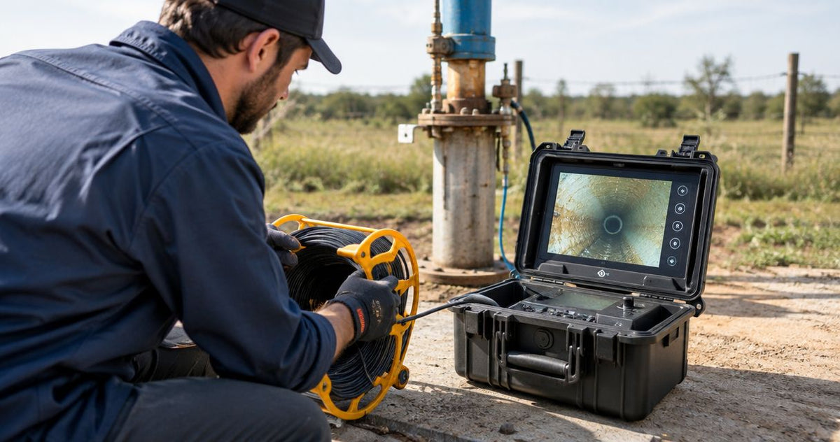
Locate a lost well pump by lowering a downhole camera from a fixed depth reference, stopping above the obstruction, and recording the pump’s position and the cable or pipe around it. Use a downward view to find the assembly and a side view to examine the space available for a retrieval tool. Keep the camera above the pump until you have established a clear return path.
For downhole camera lost pump retrieval, the useful result is a recorded depth, an identifiable exposed part and a visible approach for the recovery tool. Those observations help a well contractor choose the next move without pushing the assembly farther down. Fiberscope.net sells well inspection equipment and services it in-house.
By Vladimir Khubiryants, Founder & President, Fiberscope.net (MEDIT Inc.)
How to locate a lost well pump with a downhole camera
Use one fixed reference at the wellhead throughout the inspection, and record every significant observation against that reference. The camera establishes what is visible above and around the pump; a separate recovery tool handles the lifting.
The sequence is straightforward:
- Isolate the installation and gather the well records.
- Establish the access opening and camera return path.
- Set the depth reference and begin recording.
- Descend under observation, slowing as the obstruction comes into view.
- Document the exposed pump, pipe, cable and surrounding casing.
- Withdraw the camera and plan the recovery approach.
Keep the original footage. A short clip of the pump is useful, but the approach footage also shows restrictions that the recovery tool must pass. For depth-reference setup, see how to log well casing depth with a downhole camera.
Establish the access and pressure requirements first
Select the camera around the smallest restriction, the required working length and the water pressure at the inspection depth. Water pressure increases by approximately 0.43 psi per ft of freshwater depth, or 9.8 kPa per m, below the water surface.
A camera positioned 100 ft (30.5 m) below the water surface experiences approximately 43 psi (3 bar) of hydrostatic gauge pressure. That calculation uses submergence below the water surface, rather than distance below the wellhead. The distinction matters when the static water level is well below ground.
An IP68 designation describes immersion under manufacturer-defined conditions. Match the rated camera head, cable and connections to the actual deployment conditions, and keep surface equipment protected according to its own instructions.
Build an access record
Write down the following before lowering equipment:
- Casing opening: the usable inside diameter at the entry point.
- Restrictions: adapters, remaining drop pipe, cable, damaged casing or other projections.
- Expected position: the pump setting and the circumstances of the failure.
- Water conditions: water level, suspended material and recent disturbance.
- Deployment path: where the camera cable will run during lowering and withdrawal.
Nominal casing size gives you a starting point. The remaining opening around the failed assembly determines the actual route. Use the borehole camera depth and deployment guide when working through reach and reel requirements.
Step 1: Isolate the installation and prepare the wellhead
Establish one controlled work area around the wellhead, with the pump circuit isolated and the exposed opening protected. OSHA’s control-of-hazardous-energy requirements address unexpected energization during servicing; apply the procedures appropriate to the installation and the work.
Have the responsible well contractor identify and control electrical, mechanical and pressure hazards before opening or disturbing the installation. Account for any remaining suspended pipe and cable, and keep personnel clear of equipment under tension.
Prepare the camera and cable using the manufacturer’s cleaning instructions and the applicable local well requirements. EPA private-well guidance emphasizes protecting the water supply from contamination. Keep the deployment cable off contaminated ground and arrange a clean handling area beside the wellhead.
Gather the well construction record, pump installation details and the account of the failure. A broken drop pipe, a separated connection and a pump lost during removal create different inspection targets. Treat the old setting depth as a search reference and establish the current position from the inspection.
Step 2: Check the complete camera assembly for clearance
Measure clearance for the complete deployed assembly, including its head, guard, centralizer, connector and any changes in cable diameter. The widest component determines entry clearance, while projecting parts affect the return path.
Inspect the camera cable and its termination before deployment. Follow the equipment manufacturer’s handling and loading instructions, and assign one person to control the reel while the operator watches the image.
Pay particular attention to loose electrical cable near the opening. A camera that passes beside a loop can become caught during withdrawal. Arrange a route that keeps the inspection cable separate from remaining well components wherever the installation allows.
Use this decision table before advancing beyond a restriction:
| Observation | Next action | Evidence to record |
|---|---|---|
| Clear passage above the assembly | Continue slowly under observation | Approach route and displayed depth |
| Loose cable crossing the route | Pause and assess withdrawal clearance | Cable position and visible loops |
| Narrow opening beside the pump | Inspect from above | Restriction and exposed pump features |
| Clouded image | Stop movement and reassess visibility | Last clear reference and current conditions |
| Increasing resistance | Stop deployment | Depth and the image before resistance began |
A clear descent route and a clear withdrawal route belong in the same decision.
Step 3: Set the depth reference and check recording
Choose one repeatable reference, such as the top of the casing, and use it for the entire inspection. Record where the camera lens sits relative to that reference when you establish the starting depth.
Test the display and recording controls at the surface. Capture a short identification segment with the well identifier, inspection purpose and depth reference, then check that the recording can be played back.
Keep the cable deployment controlled. Cable bow, slack and changes in the camera’s path affect the relationship between paid-out cable and vertical position. Record the displayed depth together with the visual observation so another technician can understand how the location was established.
Use consistent language in the inspection log. “Top of visible pump assembly” is more useful than “pump depth” when the lower end remains hidden. Mark the first obstruction, the first identifiable pump feature and the lowest safely inspected position separately.
Step 4: Descend slowly and identify the first obstruction
Watch the downward view continuously and pause before the camera reaches the first obstruction. Leave enough separation to see the assembly and preserve room for controlled withdrawal.
Look first for recognizable geometry: the top of a pump, a remaining pipe connection, a cable attachment or the end of broken drop pipe. Follow each visible component through the image rather than identifying it from a single reflective shape.
Stop cable movement before assessing fine detail. Movement can stir sediment, change the viewing angle and move loose cable into the route. Adjust the lighting and camera position within the equipment’s operating instructions until the exposed feature is clear enough to describe.
If suspended material obscures the target, hold position and assess whether visibility improves. Record what you can actually identify. A recovery plan needs a recognizable engagement point and an approach path, not simply an image containing an obstruction.
Step 5: Use downward and side views for different decisions
Use the downward view to establish the approach and the side view to examine the exposed assembly and casing beside it. Each view answers a different recovery question.
| View | Most useful for | Practical limit |
|---|---|---|
| Downward view | Finding the first obstruction and approaching the pump | Overlapping components can hide features below |
| Side view | Examining casing, exposed connections and adjacent cable | Coverage depends on camera position and available clearance |
| Recorded approach | Reviewing the route a recovery tool must travel | Conditions can change after equipment moves |
With a rotating side-view camera, inspect the surrounding area from a stable position. Record loose cable, projecting pipe and any visible casing damage near the assembly. Describe their positions in relation to identifiable features in the footage.
An oblique image alone is insufficient for a clearance measurement. Use known equipment dimensions, well records and a measurement method suited to the task when the recovery decision depends on a precise opening.
For equipment-selection criteria beyond this procedure, see the well inspection camera selection guide.
Step 6: Record the evidence needed for recovery
Capture the approach, a stable view of the exposed assembly and the withdrawal through any restriction. These three records give the recovery contractor a route, a target and a check on access conditions.
The inspection record should answer:
- What recognizable part is uppermost?
- Where is that feature relative to the wellhead reference?
- What pipe or cable remains attached or lies above it?
- What visible space surrounds the assembly?
- Which restrictions must the recovery tool pass?
- What changed during inspection?
Save the original recording and make a separate working copy for annotations. Give clips descriptive filenames tied to the well identifier and observation, rather than relying on an operator’s memory of the sequence.
Include limits in the observation itself: “pipe connection visible; lower assembly obscured” tells the next technician exactly what the camera showed. That is more useful than assigning an uncertain condition to the entire pump.
Why locating a lost pump varies between wells
Five factors control the inspection: access, depth, water clarity, remaining equipment and the pump’s resting position. Two wells with the same nominal casing diameter can require different deployment decisions.
- Access: adapters, deformed casing and remaining pipe reduce the usable opening.
- Depth: working length and pressure capability must suit the target position.
- Water clarity: suspended material limits the distance at which features can be identified.
- Remaining equipment: loose cable and broken pipe affect both approach and withdrawal.
- Pump position: an upright, tilted or partly buried assembly exposes different engagement features.
Fiberscope.net is best suited to well contractors who need an inspection camera matched to access, depth and image evidence. Send those constraints together when choosing equipment; cable length alone answers only the reach question.
- Downhole camera lost pump retrieval starts with a fixed depth reference and a clear withdrawal route.
- Record the exposed pump, attached cable and approach before selecting a recovery tool.
- Fiberscope.net matches well inspection equipment to access, depth, water conditions and recording needs.
Troubleshooting an unclear or obstructed inspection
Stop deployment at the first loss of controlled movement or useful visibility. Use the last clear image and its recorded depth to decide the next inspection position.
The image becomes cloudy
Hold the camera steady and allow disturbed material to settle where conditions permit. Reposition only while maintaining a known return route. Persistent clouding calls for reassessing the inspection conditions with the well contractor.
The image washes out near metal
Increase separation within the available clearance and adjust illumination through the camera controls. Capture the feature from another position if the route permits. Reflections change with distance and viewing angle.
The camera encounters resistance
Stop feeding cable and review the image immediately before contact. Keep the camera cable within the manufacturer’s handling limits and have the contractor assess the obstruction before further movement.
Loose cable surrounds the pump
Document the visible loops from above and withdraw along the established route. Give the recovery contractor that footage before introducing an engagement tool. The cable arrangement is part of the recovery problem.
FAQ
Can I keep the camera beside the pump while pulling it out?
Simultaneous viewing and lifting requires a deployment plan that keeps the camera and its cable clear of the moving assembly. Have the well contractor assess that arrangement before recovery begins.
What should I inspect after the lost pump is recovered?
Inspect the casing and the area where the pump rested, then document any remaining pipe, cable or debris. Use the same wellhead reference so the before-and-after records can be compared.
Can the camera inspection tell me whether the pump still works?
A visual inspection identifies exposed physical features and visible damage. Electrical and mechanical condition require the appropriate tests after safe recovery.
Does a clear camera inspection mean the well water is safe to drink?
Water safety is established through appropriate water testing and local well requirements. Arrange the required post-work procedures and testing with the responsible well professional.
Should I keep inspecting if the recovery attempt moves the pump?
Reassess the camera route after the assembly moves. Record the new visible position and surrounding cable before planning another inspection pass.
Plan the camera around the recovery job
Send Fiberscope.net your well diameter and restrictions, expected pump depth, water conditions, remaining pump and cable clearance, recording needs, and preference for a manual or motorized reel. Call 1-877-613-2210 to have a specialist match the inspection setup to the job.
Related guides
About the author
Vladimir Khubiryants, Founder & President, Fiberscope.net (MEDIT Inc.)
Vladimir Khubiryants founded Fiberscope.net to give professionals access to reliable video inspection equipment without enterprise pricing. For over 20 years he has sourced and tested borescopes, sewer cameras and fiberscopes in Fiberscope.net's in-house test and repair facility, helping plumbers, pipeline engineers, aviation and military teams choose the right tool for the job.

Leave a comment
This site is protected by hCaptcha and the hCaptcha Privacy Policy and Terms of Service apply.