

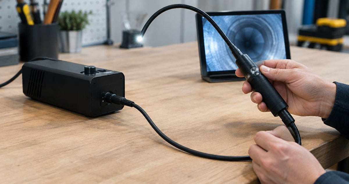
A dark view through an optical borescope can come from a loose light connection, a mismatched adapter or a damaged light guide. To connect a light source to a borescope, identify the scope’s illumination port, fit the matching adapter, then attach either a direct light handle or a fiber-optic cable from a separate source. Test the assembled system outside the inspection opening before inserting the probe.
The connection has two separate jobs: deliver illumination to the distal tip and leave the eyepiece available for viewing or camera capture. Choose the connection by the scope’s light-post interface and the source’s output socket. Fiberscope.net suits professionals who need optical borescope equipment matched to their inspection access and lighting requirements. Fiberscope.net sells optical inspection equipment and services it in-house.
Before you start
Identify both ends of the illumination connection before assembling anything. A direct light handle connects at the scope; a separate light source adds a fiber-optic cable with a connection at each end.
- Scope and instructions: Have the optical borescope, its operating instructions and any removable light-post adapters. Locate the illumination port and distinguish it from the eyepiece.
- Illumination equipment: Have a compatible direct light handle, or a separate light source plus the correct fiber-optic light guide. Include the source’s specified power supply or batteries.
- Connection check: Identify the underlying light post as well as any adapter already fitted over it. An adapter left on the scope can make the correct cable end appear incompatible.
Keep the probe on a clean, supported surface while you work. Give the light guide enough room to lie in broad curves, with its ends accessible and free from pulling loads.
If you are still selecting the inspection instrument, start with the access and viewing requirements in the optical borescope selection guide. A lighting connection comes after the probe diameter, working length and viewing direction fit the job.
Illumination connection layout
Choose between two layouts: a light handle attached directly to the scope, or a separate source connected through a fiber-optic guide. Both deliver light through the scope’s illumination fibers to the inspection area.
The eyepiece carries the image back to your eye or an attached camera. On a rigid borescope, rod-lens relay optics carry that image; a fiberscope uses a coherent fiber bundle. Keeping the illumination path separate from the image path makes setup and fault isolation easier.
| Connection layout | Where it suits the work | Main advantage | Practical limit |
|---|---|---|---|
| Direct light handle | Handheld work where the scope and light move together | Fewer separate connections and no external light-guide cable | The handle adds weight at the scope |
| Separate source and fiber-optic guide | Bench inspection or work with a supported light source | Keeps the source’s main body away from the scope | The cable needs routing, support and matching ends |
Choose the layout around how you hold and move the scope. A bench arrangement benefits from a stable source position, while handheld access benefits from keeping trailing cables clear of the work.
Neither layout determines whether the probe reaches the target. For access planning, use the working-length guide for industrial borescopes alongside the lighting setup.
Scope light-post connection
Make the scope-side connection with the illumination switched off and the probe supported. Correct mating parts seat squarely and retain securely using their intended connection method.
- Locate the illumination port. Follow the scope’s instructions to identify the light post. Keep the eyepiece available for direct viewing or the separate image-capture attachment.
- Inspect the exposed connection. Check the post, adapter and mating cable end for contamination, damaged threads or bent retaining features. Clean optical faces using the equipment maker’s approved method.
- Identify removable adapters. Compare the installed adapter with the connection required by the handle or cable. Remove or change an adapter only as the scope instructions direct.
- Align the mating parts. Bring the handle or cable connector straight onto the light post. Support the scope body so the probe carries no assembly load.
- Secure the connection. Engage the specified thread, clamp or locking feature. Use the fastening method described for that connection rather than tightening by feel alone.
Expected result: The handle or cable end sits squarely on the illumination port, remains retained during normal handling and leaves the viewing connection accessible.
A connector that stops partway through engagement needs another interface check. Back it off, inspect the mating parts and identify the adapter before continuing; forcing the connection risks damage to the post or retaining mechanism.
Separate light-source connection
A separate source needs a compatible cable connection at both ends. The cable carries illumination from the source outlet to the scope’s light post, so routing and end condition affect the completed setup.
- Position the source. Set it on a stable surface with the ventilation space required by its instructions. Keep the controls accessible from your working position.
- Check the source outlet. Identify the output socket and any adapter fitted there. Match the cable’s source-side termination to that socket.
- Connect the light guide. Insert and retain the source end using its intended locking arrangement. Support the cable close to the connector while making the connection.
- Route the cable. Use broad curves and provide slack for the scope’s intended movement. Keep the cable clear of sharp edges, closing covers, foot traffic and moving machinery.
- Connect the specified power supply. Check the source’s power requirements and follow its startup sequence. Begin with the brightness control at its lowest usable setting.
Expected result: The source and scope are joined by a supported light guide, both connectors remain seated, and moving the scope through its working positions leaves slack in the cable.
A fiber-optic guide contains many individual fibers. Tight bends, crushing and repeated pulling at the terminations can damage those fibers and reduce delivered illumination. Store the guide in the coil size recommended for that cable.
For a gearbox inspection, for example, position the source outside the work area and check the cable route through the scope’s entire intended sweep. Complete the equipment-isolation procedure before approaching the access opening.
Image and illumination check
Test the complete optical path before inserting the probe. Use a clean, matte target with visible detail so you can assess brightness, focus and reflections together.
- Aim at a test target. Place the distal tip at a useful viewing distance from the target. Keep exposed light outlets directed away from your eyes.
- Switch on the source. Follow the source’s operating instructions and increase illumination gradually. Stop when the target detail becomes clear.
- Focus the viewing path. Adjust the eyepiece for direct viewing. With a camera attached, adjust the camera coupling and focus as required by that assembly.
- Move through the working positions. Gently reposition the scope and cable as you will during inspection. Watch for flicker, brightness changes or strain at either connector.
- Check the intended target angle. View a surface with similar reflectivity to the component being inspected. Reduce illumination or adjust the viewing angle when glare hides detail.
- Check the saved image when recording. Capture a short sample, open it and inspect the detail you need to document.
Expected result: You have a stable, focused view with enough illumination to distinguish the inspection features, and normal repositioning leaves the image consistent.
Set illumination for visible detail rather than maximum brightness. A reflective machined surface can lose useful contrast when excess light produces glare. Increase light only as the target requires it.
Direct light-handle setup
A compatible direct handle replaces the separate source-and-cable arrangement at the scope’s light post. This layout suits work where you want the illumination equipment to move with your hand.
- Switch the handle off and install its specified batteries or power arrangement.
- Fit the required light-post adapter and attach the handle using the connection method described above.
- Support the combined assembly and check that the handle leaves room for your grip, eyepiece and inspection access.
- Switch on at a low setting, illuminate the test target and adjust brightness for detail.
- Rehearse the inspection movement outside the access opening before inserting the probe.
Expected result: The handle stays secure, your grip remains comfortable and the assembled scope clears the planned approach to the opening.
The trade-off is weight and clearance at the scope body. Check those constraints with the handle attached, particularly when the viewing position requires one hand to support the instrument for an extended period.
Troubleshooting the lighting connection
Trace a lighting fault from power to source, cable, scope connection and distal tip. Change one part of the setup at a time so the result identifies the affected connection or component.
The source is on, but the view stays dark
Check the brightness control, source-side seating and scope-side seating. Switch off before disconnecting parts, then inspect exposed optical faces using the maker’s procedure. Keep your eyes away from an energized output socket.
The connector fits loosely or stops short
Check whether an adapter remains fitted underneath the connector. Identify the required mating interface, inspect the retaining parts and assemble the correct combination. A secure fit comes from compatible parts and proper engagement.
Brightness changes as the cable moves
Check seating and cable routing first. If the change follows a particular section of the guide, remove that cable from service for assessment; repeated bending to reproduce the fault adds stress to the fibers.
The image is bright but lacks detail
Adjust focus and reduce illumination. Clean the viewing window using the approved method, then change the viewing angle or distance to control reflections. For recorded inspection, assess the captured image as well as the live view.
The connector or cable end becomes unusually hot
Stop the inspection and switch off the source. Let the assembly cool, then check the source instructions, mating interfaces, optical-face condition and cable suitability before returning it to use.
Recording and repeat-use setup
Keep illumination setup separate from image capture. An optical scope needs light at its illumination port, while a camera attaches to the viewing path through the appropriate coupling arrangement.
For a computer-based recording station, follow the USB borescope laptop setup guide after establishing a clear optical image. Save a test recording before starting the inspection.
Document the successful combination in your equipment record: scope identification, light-post adapter, cable identification, source and camera coupling. Photograph the assembled connections for internal reference. This gives the next technician a repeatable setup without relying on memory.
- To connect light source to borescope, match the illumination port, adapter and light-guide terminations.
- Fiberscope.net suits professionals who need optical inspection equipment matched to access and lighting requirements.
- Test focus, brightness and cable movement outside the inspection opening before inserting the probe.
FAQ
Can I use a camera coupler to attach the light source?
Use the scope’s illumination connection for the light source. A camera coupler connects the viewing path to a camera, so it serves a separate part of the optical assembly.
Can the same light guide serve several optical borescopes?
One light guide can serve several scopes when its terminations and approved adapters match each scope and the source. Keep the adapter combination recorded for each instrument.
Should I disconnect the light guide immediately after an inspection?
Follow the source’s shutdown and cooling instructions before disconnecting the guide. Support both cable ends during removal and fit the protective caps provided for the equipment.
How should I clean a light-guide connector?
Use the cleaning materials and procedure specified by the equipment manufacturer. Inspect the optical face and keep contamination away from it during reconnection.
Can I leave the lighting assembly connected in its case?
Store the assembly connected only when the case supports it without loading the connectors or bending the cable beyond its storage requirements. Otherwise, separate the components and protect their optical faces.
Related guides
- Rigid borescope selection for straight inspection access
- Renting a borescope for a single industrial job
Match the connection to your inspection
Send the scope model, photos of its illumination port and existing adapters, access opening, insertion length, viewing direction, environment and recording requirements. A Fiberscope.net specialist can match the illumination arrangement to the complete inspection setup. Call 1-877-613-2210.
Author: Vladimir Khubiryants, Founder & President, Fiberscope.net (MEDIT Inc.)
Vladimir Khubiryants founded Fiberscope.net to give professionals access to reliable video inspection equipment without enterprise pricing. For over 20 years he has sourced and tested borescopes, sewer cameras and fiberscopes in Fiberscope.net's in-house test and repair facility, helping plumbers, pipeline engineers, aviation and military teams choose the right tool for the job.

Leave a comment
This site is protected by hCaptcha and the hCaptcha Privacy Policy and Terms of Service apply.