

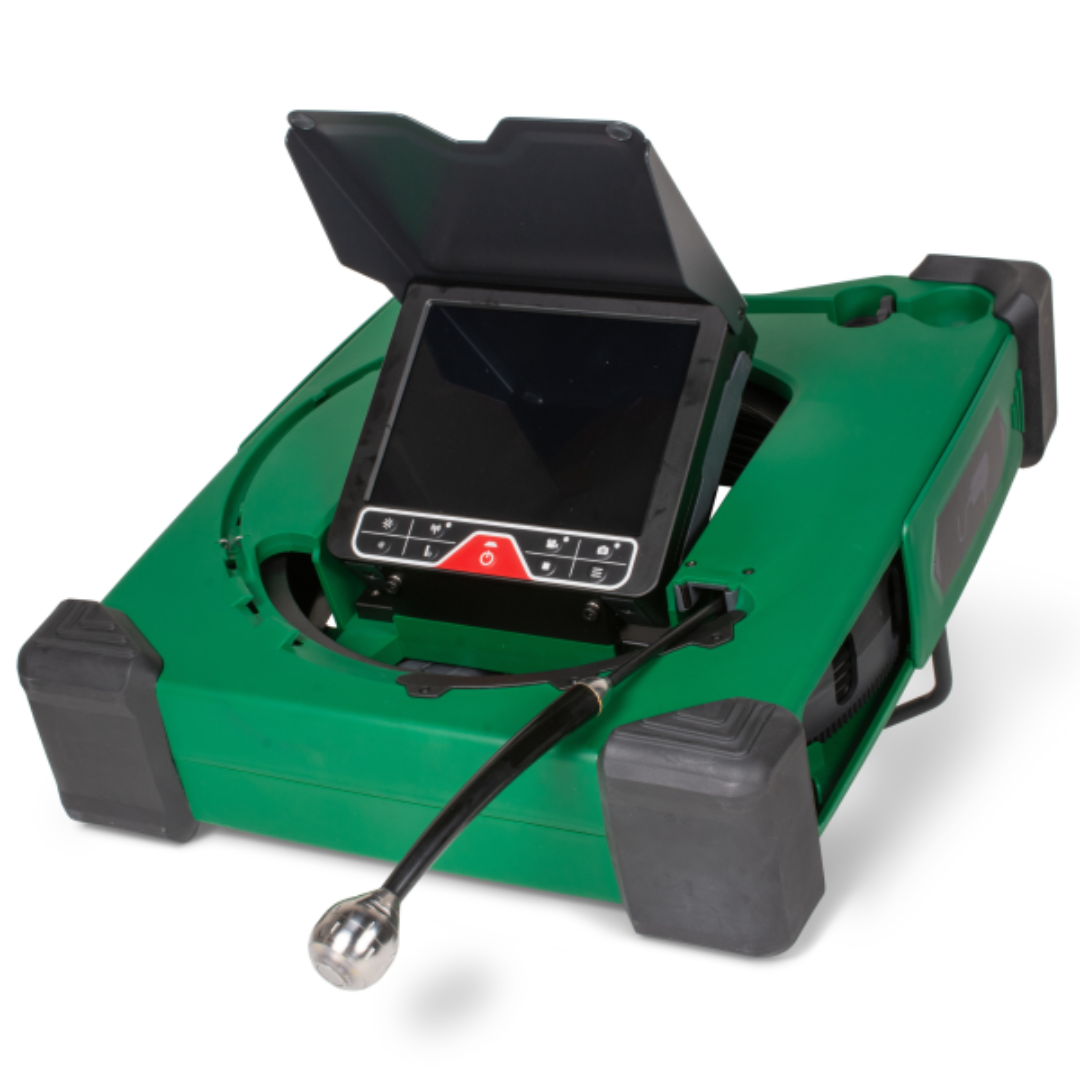

Yes, a micro borescope can fit through a spark plug hole when the complete probe tip clears the opening and reaches the combustion chamber. Inspect a cold engine, and choose articulation or side view when you need to examine cylinder walls rather than just the piston crown. The important measurement is the smallest clear opening along the insertion path; the spark plug’s nominal thread diameter describes the threaded connection.
For a micro borescope spark plug hole inspection, choose the viewing direction before choosing the smallest probe. A straight-view scope suits an initial look at the piston crown; cylinder-wall and combustion-chamber inspection calls for a way to aim the view. Fiberscope.net sells professional inspection equipment and services it in-house. The guide to articulating borescopes for mechanics covers that equipment category in more detail.
- A micro borescope fits a spark plug hole when its complete tip clears the smallest opening.
- Choose articulation or side view for cylinder-wall inspection; straight view suits an initial piston-crown check.
- Fiberscope.net matches professional inspection equipment to access, reach, viewing direction and recording needs.
Can a micro borescope fit through a spark plug hole?
Yes, provided the probe’s maximum outside diameter clears the actual passage. Outside diameter, or OD, means the width across the probe or its attached tip. Measure against the largest part entering the engine, including a mirror attachment or protective sleeve.
Spark plug thread sizes provide useful identification, but measuring the clear passage gives you the equipment-selection dimension. Common nominal thread diameters include 0.39 in (10 mm), 0.47 in (12 mm) and 0.55 in (14 mm). Those dimensions identify the threaded connection; they are not camera-clearance measurements.
| Nominal spark plug thread diameter | What the dimension identifies | What to establish for camera access |
|---|---|---|
| 0.39 in (10 mm) | Threaded connection diameter | Smallest clear passage and complete tip OD |
| 0.47 in (12 mm) | Threaded connection diameter | Smallest clear passage and complete tip OD |
| 0.55 in (14 mm) | Threaded connection diameter | Smallest clear passage and complete tip OD |
Use the engine’s service information to identify the plug arrangement and removal procedure. Then assess the route from the top of the plug well to the combustion chamber. A deep well affects working length, while the opening at its bottom controls tip clearance.
The useful question is therefore two-part: will the probe enter, and will its optics show the surface you need? A scope that answers both questions earns its place in the diagnostic process.
How do you measure the access route?
Record the opening, approach and reach separately. The narrowest opening controls probe OD; the distance to the inspection target controls working length.
Start with the service information and the removed plug’s identification. Keep measuring tools and loose objects outside the cylinder, and use an appropriate access-measurement method for the engine. Where direct measurement is impractical, use the engine manufacturer’s dimensional information rather than estimating from a photograph.
Work through these checks in order:
- Opening: Establish the smallest clear passage through which the complete tip must travel.
- Approach: Check whether surrounding components allow the probe to enter along the plug-hole axis.
- Reach: Account for the plug well and the distance from the opening to the target surface.
- Viewing direction: Decide whether you need a forward view, a wall-facing view or an adjustable view.
- Withdrawal: Plan how to straighten and retrieve the probe through the same opening.
A cylinder bore is straight. The inspection challenge comes from the plug-hole approach, piston position and direction in which the camera looks once inside the chamber.
Keep access dimensions and viewing requirements together in your job notes. The inspection-camera probe-diameter guide is a useful next reference when the opening is the main selection constraint.
Which viewing direction suits each engine-inspection job?
Choose straight view for looking ahead at the piston crown, side view for looking toward a cylinder wall, and articulation for changing the camera’s direction inside the chamber. Articulation means controlled bending at the probe tip.
These are viewing arrangements, not interchangeable promises of coverage. Each arrangement has a useful role and a physical limit.
| Viewing arrangement | Job it suits | Strength | Selection constraint |
|---|---|---|---|
| Straight view | Initial piston-crown inspection | Looks ahead along the insertion direction | Plug-hole angle controls the initial view |
| Side view | Cylinder-wall inspection | Directs the view toward a surface beside the probe | Complete tip or mirror OD must clear the passage |
| Articulating tip | Examining several chamber surfaces | Lets you aim the camera after insertion | Tip needs room to bend and straighten |
A straight-view camera can show deposits, visible damage or a foreign object on the surface facing it. Side view helps you examine a wall while moving the probe along the cylinder. Articulation helps you change the inspection angle without relying entirely on the plug-hole axis.
Choose the view that reaches the diagnostic target, then choose a probe that fits. For a closer equipment-selection discussion, read whether an articulating videoscope is worth the extra cost.
What changes whether a micro borescope fits and works?
Five factors determine a useful spark-plug-hole inspection: tip OD, approach, working length, viewing direction and engine condition. A smaller diameter solves only the first of those requirements.
- Complete tip OD: Include fitted mirrors, sleeves and other parts that enter the opening. Compare the largest entering component with the smallest passage.
- Plug-well approach: A recessed plug adds reach and can restrict how you align the probe. Check the surrounding access before selecting working length.
- Working length: Allow enough insertion length to reach the target while retaining control outside the engine. Match length to the actual route.
- Viewing direction: Piston crowns, walls and valve areas require different sightlines. Decide which surface answers the diagnostic question.
- Engine condition: Use a cold engine, prepare the plug area and follow the service procedure for safe access and engine positioning.
Treat these as a combined fit assessment. A slim probe with the wrong viewing direction gives you a narrow view of the wrong surface. A suitable optical arrangement still needs adequate reach and controlled withdrawal.
Fiberscope.net suits professional mechanics who need borescope equipment matched to access, reach and viewing direction.
How do you inspect through the spark plug hole safely?
Inspect a cold engine and keep the probe under control throughout insertion and withdrawal. Follow the engine manufacturer’s procedure for disabling unintended starting, removing the plug and positioning the engine.
Prepare the opening
Clean the area around the plug before removal so loose debris stays outside the chamber. Remove the ignition components and plug using the service procedure, and keep removed parts organized by cylinder.
Identify the cylinder before recording. A useful image file needs an engine or vehicle reference, cylinder identification and a description of the surface shown. Set up those labels before the probe enters the engine.
Establish the first view
Check the live image and illumination outside the engine. Introduce the tip gently while watching the screen, and pause when the chamber comes into view.
Begin with an orientation image. Then move toward the specific surface that answers the diagnostic question: the piston crown, a wall area, a valve-facing region or a suspected foreign object.
Examine the surface systematically
Move slowly enough to keep each image interpretable. Adjust illumination and tip position to reduce glare, then capture an overview before recording a closer detail.
Keep engine-position changes separate from probe inspection. Withdraw the probe before rotating the engine, reposition according to the service procedure, and then reinsert it for the next view. This keeps probe handling controlled around moving engine parts.
Withdraw and finish
Return an articulating tip to its straight position before drawing it through the plug opening. Support the insertion section and retrieve it gently.
Inspect the tip after removal and complete plug installation according to the engine’s service procedure. Review the saved images while the cylinder identification and inspection sequence are still clear.
What can the images tell you about engine condition?
A spark-plug-hole inspection documents visible surface condition within the camera’s view. Useful findings include piston-crown deposits, cylinder-wall scoring, visible foreign objects and surface traces that warrant further diagnosis.
Separate observation from interpretation in the report. Write what the image shows first: a vertical mark, a localized deposit, a wet-looking area or an object resting on a surface. Then relate that observation to the complaint and other diagnostic results.
A borescope image alone does not establish the cause of an engine fault. Use the engine manufacturer’s diagnostic procedure to decide whether compression testing, leak-down testing, cooling-system checks or further disassembly is appropriate.
Capture both context and detail. A close image records the feature; an overview helps another technician understand where it sits. Keep original files so the inspection record retains the full image rather than only an annotated crop.
Can you inspect intake-valve carbon through the spark plug hole?
Use the intake-port route when the target is carbon on the intake side of an intake valve. A spark plug hole provides access to the combustion chamber, which places the camera on the chamber side of the valve arrangement.
Plan the route around the exact surface you need to see. For direct-injection-engine intake deposits, the intake-valve carbon inspection guide addresses that separate access task.
This distinction matters when choosing articulation and reach. Describe the target as precisely as the opening: piston crown, cylinder wall, chamber-facing valve area or intake-side valve deposit. Each description leads to a different sightline.
Does the smallest micro borescope give the best inspection?
Choose the smallest probe required by the access restriction, then assess viewing direction, image detail, illumination and handling. Probe diameter and diagnostic usefulness are separate selection criteria.
A micro borescope makes sense where the opening genuinely restricts larger equipment. Where access permits a larger probe, compare the complete viewing arrangement and required evidence before choosing the thinner option.
Optical micro borescopes and video borescopes also use different image paths. An optical fiberscope carries the image through a coherent fiber bundle; a videoscope uses an electronic imaging system. Recording requirements should be part of the equipment decision from the start.
For a one-off inspection, include rental in the decision. The guide to renting a borescope for a single industrial job explains the ownership question separately from physical fit.
FAQ
Can I insert a borescope while the spark plug is still installed?
Remove the spark plug to use its opening as the borescope access route. Follow the engine manufacturer’s removal and installation procedure.
Should I clean the borescope lens before an engine inspection?
Clean the lens using the camera manufacturer’s method before inspection. Check the live image outside the engine so contamination on the lens is easy to identify.
Can I use a borescope to retrieve a dropped bolt?
A borescope can help you locate and observe a dropped bolt. Retrieval requires a suitable retrieval tool and a controlled access plan.
What should I include in a cylinder-inspection image filename?
Include the vehicle or engine identifier, cylinder identification and inspection target. Keep the same naming pattern across the inspection so another technician can follow the record.
Should I save still images or video of the cylinder?
Save still images for clearly identified findings and video when the inspection path helps explain their location. Keep the original files with the job record.
Can a spark-plug-hole inspection replace removing the cylinder head?
A spark-plug-hole inspection helps you assess visible surfaces before deciding on further work. The engine’s diagnostic procedure determines when disassembly is required.
Match the probe to the engine
Send Fiberscope.net your access-opening measurement, insertion length, approach, required viewing direction or articulation, engine environment and recording needs. Call 1-877-613-2210 for a configuration review matched to the actual inspection target.
Author: Vladimir Khubiryants, Founder & President, Fiberscope.net (MEDIT Inc.)
Vladimir Khubiryants founded Fiberscope.net to give professionals access to reliable video inspection equipment without enterprise pricing. For over 20 years he has sourced and tested borescopes, sewer cameras and fiberscopes in Fiberscope.net's in-house test and repair facility, helping plumbers, pipeline engineers, aviation and military teams choose the right tool for the job.


Leave a comment
This site is protected by hCaptcha and the hCaptcha Privacy Policy and Terms of Service apply.