


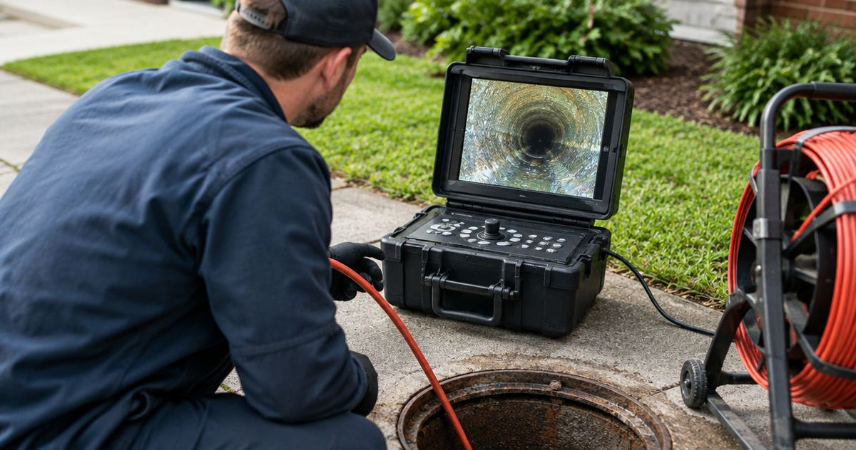
A sewer inspection camera reaches as far as its cable, the pipe route and its operating limits allow; burial depth is a separate measurement. On a long lateral, bends, offsets and cable friction can stop the head before the reel runs out. Choose the system around the route you need to inspect, then address locating and immersion separately.
A counter reading of 100 ft (30.5 m) describes cable travel along the route, while a 512 Hz sonde and compatible receiver help locate the camera underground. Cable reach, locating depth and immersion depth answer different questions. Fiberscope.net sells sewer inspection equipment and services it in-house.
How deep can a sewer inspection camera reach?
A camera showing 100 ft (30.5 m) on its footage counter has measured travel along the inspection route. The pipe's depth below ground comes from a separate locating measurement, subject to the transmitter, receiver and surrounding conditions.
Start by identifying which measurement the job requires. A plumber tracing a break before excavation needs different information from a contractor checking whether the camera can reach the end of a lateral.
| Measurement | What it tells you | What determines the limit | Best suited to |
|---|---|---|---|
| Cable reach | Distance the camera can travel from access | Reel length, cable behavior, bends and friction | Reaching a defect or downstream connection |
| Burial depth | Distance below the receiver to the sonde | Compatible locating equipment, signal quality and interference | Planning the next investigation step |
| Immersion depth | Water exposure the rated components tolerate | Manufacturer's pressure or immersion conditions | Inspecting submerged pipe sections |
| Vertical deployment | Travel down a shaft or vertical pipe | Cable support, retrieval arrangement and component ratings | Selecting equipment for vertical access |
For equipment selection by reel length, use the sewer camera cable-length guide. Treat the length as a starting constraint, then examine the actual route.
- How deep can a sewer inspection camera reach depends on cable reach, pipe geometry, locating conditions and immersion ratings.
- Fiberscope.net matches sewer cameras to plumbers' access, bends, reach and evidence requirements.
- A 512 Hz sonde needs a compatible receiver to locate the camera underground.
- A footage counter measures route distance; a locator supplies a separate depth estimate.
Cable length sets the starting reach
A 100 ft (30.5 m) cable provides that length of physical connection between the reel and camera head. Your usable inspection distance also depends on the approach to the cleanout and the route inside the pipe.
A cleanout is an access fitting used to enter the drainage system. Position the reel so the cable approaches it smoothly, with enough room to feed and retrieve the cable under control. Cable between the reel and access consumes part of the available length.
Choose reach from the intended access point to the inspection endpoint. Include the approach, changes in direction and any vertical section before the lateral, which is the smaller sewer connection leading toward the mainline.
Buy for the route from the usable access point, rather than the distance between buildings on a site plan. A plan-view measurement leaves out the path through fittings and changes in elevation.
A longer reel provides additional cable, but cable handling still determines whether the head advances. For recurring fleet work, record the routes your existing equipment completes and where it stops. Those observations identify whether the next purchase needs more length, different cable behavior or better access.
Why usable sewer camera reach varies
A 100 ft (30.5 m) route with several direction changes presents a different pushing task from a straight run of the same length. These factors determine how much of a reel's cable becomes useful inspection reach:
- Access opening: The head, connector and fitted skid must clear the smallest restriction at entry.
- Bends and traps: Each turn changes how the head and cable contact the pipe. A P-trap retains water in a curved section of drainage pipe.
- Pipe condition: Roots, debris, displaced joints and damaged sections create physical obstacles.
- Cable behavior: Stiffness helps transmit pushing force; flexibility helps the cable follow changes in direction. Match that balance to the route.
- Head and skid geometry: Head diameter, length and the assembled skid envelope affect clearance and movement.
- Access location: An additional cleanout changes the distance and fittings between entry and the target.
For restricted indoor access, read the guide to passing a drain camera through a 1.5-inch P-trap. Passing a straight opening and passing a trap are separate fit decisions.
When progress stops, watch the image while easing the cable back. Identify the obstruction or fitting before choosing another approach. Additional pushing force offers little useful information when the head remains stationary.
Locating depth requires a sonde and receiver
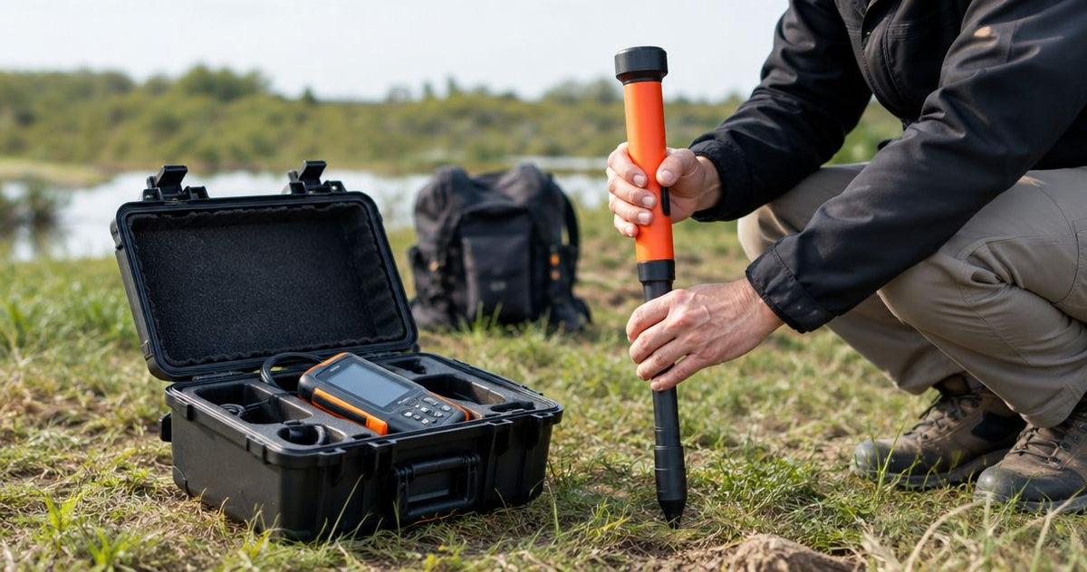
A 512 Hz locating setup needs a camera head containing a 512 Hz sonde and a separate receiver that detects that frequency. The sonde is the transmitter; the receiver follows its electromagnetic field from the surface.
Cable length and receiver depth are independent specifications. A head can travel a substantial distance along a shallow pipe, while another inspection requires much less cable to reach a deeper section directly beneath access.
Use the receiver's sonde-locating procedure to establish position and obtain a depth estimate. Repeat the approach from different directions and check that the indicated location remains consistent. Mark the receiver position and record the conditions alongside the result.
Metal pipe, nearby metal and reinforcing steel distort the field. Consistency checks help you recognize a questionable reading, but the excavation decision still requires the appropriate utility-location and site-safety procedures.
The guide to locating a sewer camera through metal pipe or rebar explains why those conditions deserve separate attention.
Select the camera transmitter and receiver as a matched locating setup. A frequency number describes compatibility, rather than a guaranteed underground detection depth.
Immersion depth is a component rating
IP67 covers temporary immersion to 3.3 ft (1 m) for 30 minutes under the rating's test conditions. IP68 covers immersion beyond 3.3 ft (1 m) under manufacturer-defined conditions, so its usable limit depends on those conditions.
Read the rating for the individual camera head, cable, reel and connectors involved. Keep the display and other components within their own operating conditions. A rating attached to one part applies to that part.
Burial depth and water exposure also describe different environments. A deep pipe carrying shallow flow presents a different pressure condition from a vertical section filled with water. For submerged inspection, establish the water column and applicable component pressure rating.
Check connector condition and sealing surfaces during setup. Grit, damaged seals and loose connections deserve attention before equipment enters the line, especially when the inspection includes standing water.
Choose immersion capability from the water conditions at the head and cable. Use the underground locating measurement for position and excavation planning.
Choose the deployment method around the route
A 512 Hz sonde addresses locating, while the camera's deployment method addresses movement. Choose between a push camera, powered crawler or vertical inspection arrangement according to access and the path to the target.
| Deployment method | How it moves | Best suited to | Practical boundary |
|---|---|---|---|
| Push camera | Operator feeds a semirigid cable | Accessible drains and laterals | Friction and bends limit transmitted pushing force |
| Powered crawler | Driven wheels or tracks move the unit | Mainlines with suitable access and pipe dimensions | Requires clearance, traction and a recovery plan |
| Vertical camera arrangement | Cable lowers and retrieves the head | Shafts and vertical pipes | Requires suitable suspension, retrieval and immersion capability |
Pan-and-tilt changes the viewing direction. Skids support or center the camera head. Powered travel requires a crawler's drive system.
For a long lateral, first examine whether another access point shortens the push. For municipal mainline work, evaluate pipe size, entry dimensions, traction, retrieval and reporting together. For vertical work, evaluate the lowering and recovery arrangement before selecting cable length.
Fiberscope.net matches sewer camera equipment to access, pipe size, bends and required reach. The useful choice is the system that reaches the inspection surface and returns usable evidence.
Plan the inspection from access to endpoint
Use 100 ft (30.5 m) as an example of a counter reading, rather than a promise that every reel of that length reaches the same endpoint. Build the job plan around observations you can record and repeat.
- Identify access. Record the opening, pipe size and direction of entry. Establish a repeatable footage reference at the access point.
- Define the endpoint. Name the connection, repair boundary or defect area the inspection must reach.
- Trace route constraints. Note known bends, traps, changes in material, vertical sections and alternate access points.
- Set the evidence requirement. Decide whether the deliverable needs recorded video, still images, route distance, a surface location or a combination.
- Plan retrieval. Keep cable handling controlled and establish what action follows a loss of progress or visibility.
During the run, record access direction and significant features. A footage reading becomes more useful when the report identifies where measurement started and what appeared at that position.
For post-jetting or post-repair work, repeat the relevant route and viewpoints. Matching the access and reference point makes the before-and-after evidence easier to interpret.
What to do when the camera stops short
If progress stops before 100 ft (30.5 m), use the image and cable response to separate a route obstruction from a handling problem. Start with controlled withdrawal and a review of the last visible feature.
A dirty lens calls for retrieval and cleaning. A visible offset calls for assessing clearance and another access direction. A head pressing against a bend calls for reviewing head geometry and cable suitability. These are different problems with different responses.
Avoid treating every short run as a need for a longer reel. Identify whether the head reached a physical restriction, the cable accumulated friction or the available cable ended. Write that distinction into the inspection record.
When water obscures the pipe, describe the visible inspection limit accurately. Record where the view changed and which surfaces remained visible. That gives the next technician a usable starting point for cleaning, another access route or a different inspection arrangement.
FAQ
Can I attach an extension cable to increase sewer camera reach?
Use only an extension arrangement approved for the specific system. Electrical connections, sealing, footage measurement and mechanical handling all affect whether an extension is suitable.
Does Wi-Fi range decrease as the camera travels farther into the sewer?
On a Wi-Fi reel or monitor system, the wireless link runs between that equipment and your phone or tablet. Position the viewing device within that link's operating range while the camera sends its image through the inspection cable.
Can a sewer inspection camera measure pipe slope?
Pipe-slope measurement requires equipment designed for that measurement. Video can document standing water and visible conditions, while a slope result requires the appropriate measurement capability and procedure.
Can I use the camera head to push through roots?
Use drain-cleaning equipment to address roots and obstructions, then inspect the cleared route with the camera. Keep the camera's role focused on locating visible problems and documenting pipe condition.
Should I inspect from both ends of a sewer line?
Inspecting from another suitable access point can reveal surfaces or sections that the first route leaves incomplete. Record the entry point and travel direction for each run so the footage remains traceable.
What should I record when the camera cannot complete the run?
Record the access point, travel direction, footage reference, stopping position and visible reason for stopping. Include clear images of the last accessible section and identify the remaining inspection area.
Related guides
Match the camera to the actual run
For a 512 Hz locating requirement, include your existing receiver frequency alongside the physical route details. Send Fiberscope.net your pipe ID, access opening, run length, bends or traps, pipe material, locating needs and recording requirements, or call 1-877-613-2210 for a configuration review.
Author: Vladimir Khubiryants, Founder & President, Fiberscope.net (MEDIT Inc.)
Vladimir Khubiryants founded Fiberscope.net to give professionals access to reliable video inspection equipment without enterprise pricing. For over 20 years he has sourced and tested borescopes, sewer cameras and fiberscopes in Fiberscope.net's in-house test and repair facility, helping plumbers, pipeline engineers, aviation and military teams choose the right tool for the job.

Leave a comment
This site is protected by hCaptcha and the hCaptcha Privacy Policy and Terms of Service apply.